
Foundation, Concrete and Earthquake Engineering

Foundation Settlement Due to Vibration

Generally vibration occurs in foundation when pile driving and blasting operation are done. This may be a part of construction operation of surrounding under construction buildings or for the new structure, that’s soil settlement are considered in design. The both operations are performed as a concept of compacting loose sand and subsidence is expected for new building but not expected for existing neighbor building if any.

As an example in a loose deposit of cohesionless soil 100 piles of 50 ft length were driven for same purpose of compaction. The result were occupied ground area settled 6 in. It was noticed that the settlement gradually decrease apart from pile driving area as an example at 50 ft apart the settlement was recorded only 1/8 in. So foundation engineers should be conscious about pile driving in such loose sand to avoid damage to surrounding structure. Sometimes other construction options are to be chosen leaving such vibration type foundation treatment.
Epoxy Grouts to reduce vibration from machine provided on foundation
Another source of vibration is arrived from machine foundation. It is very important to design machine foundation to have a period that has safe difference from the period of
Thickened foundation for machine foundation to absorb vibration.JPGadjacent soil to avoid possible resonance. Normally foundation weight is increased to absorb vibrations and distinguish period of both soil and foundation. There have a thumb rule of providing 2.5 times weight to foundation than that of machine to be supported.

Now, which type of soils suffers more due to vibration?
he cohesive soil suffers less impact from vibration. But alarming increment of relative density of cohessoinless soils are observed in this regard. This condition becomes worse to sands under water table or sand that is relatively dry. But sands above water table sometimes show sufficient cohesion not to re-arrange grain structure.

Erection Safety of Pile Rig

We all are concern with piling operation, investigating damaged pile, pile cap design and casting and other operation followed by them. But we are little concern with safety against piling hazard. In this post, we discuss erection of pile rig.

The frames of pile rigs must be checked safe structurally for expected dead, operational load and wind loads. If engineer in charge doubts structural strength, relevant test should be conducted to ensure any failure during operation or idle time. Every pile driving and operational equipments should be inspected and certified as safe. Guy line from all direction of flying hammer
In case of large project where two or more rigs are working at a time, a separation of distance more than longest leg of two rigs should be kept. 
Pile rig erection safety
Concrete beds, firm timber sills or any other secure foundations should be used as support of pile drivers. Sometimes pile drivers are guyed to withstand storm, wind, earthquake or other lateral impact. Normally three guys are required to have a least resistance to such impact. This safety measures are equally applicable to the rigs that are not even in use. Pile driver uplift

How can bearing capacity of shallow foundation be determined from permissible settlement?

This post concerned with plate bearing test. At first we have to know what plate bearing test. By this field test ultimate bearing capacity of soil and its settlement under designed load can be determined. In this test a steel plate is loaded at foundation level and settlement respective to load increment are recorded. The loads are gradually increased until the steel plate sinks at rapid rate. The ultimate bearing capacity of soil at foundation level is determined by the load at which plate sinks rapidly divided by area of steel plate. As we know, safe bearing capacity is a fraction of ultimate bearing capacity. This fraction is call factor of safety.
load-settlement curve from plate bearing test
A plot, known as load-settlement curve, on logarithmic scales (log-log plot) are done with load intensity as ordinates and settlement values as recorded in test as abscissa. In the plot two straight lines are found. The yield value or yield point is determined from intersection of two lines. This yield point is important in this discussion.

Now question is how to use this value. We realized, so far, in this discussion that safe bearing capacity is closely related to settlement of footing. The above load settlement curve provides ultimate bearing capacity and hence safe bearing.

The load intensity corresponding to yield point is the ultimate bearing capacity. From which using factor of safety 2-3 the safe bearing capacity is determined. This is safe bearing capacity for settlement.

The actual safe bearing capacity should smaller of following two:

a. Safe bearing capacity from settlement as derived from load-settlement curve.

b. Safe bearing capacity on the basis of shear failure

Piles in Tension in Pile Group

Generally the number of pile is determined by the axial load divided by capacity of each pile considering both end bearing and skin friction. But actual situation is there have always some reactions from lateral forces like earthquake and wind forces to piles as axial force, moment and shear force. The axial force is treated as usual. But the moment makes the differences in design and anchorage properties of both in pile and caps. In case of moment in pile cap, total reaction on each pile can be found by the expression below:
tension pile equation
Where, P=sum of reactions that are resulted from axial and moment

∑V= total vertical loads on foundation

n= number of piles in pile group
special anchorage for tension pile to pile cap
∑M=this is the sum of moments that have discussed above. The moment is not about center of gravity of cap but about center of gravity of pile group.

d= distance from the respective piles to the center of gravity of pile group.

If the p is positive there is no question of uplift and necessary anchorage. But if p is negative and piles in group are not anchored to pile caps the only a part of piles in pile group are in compression up to neutral axis. As the rest piles are not anchored to pile cap, these piles become ineffective as neither compression nor tension reactions are developed in them. The worse situation is, as some portion of piles in group is ineffective the compression reaction on the active piles is increased.

Thus it can be concluded that if piles in group are capable to withstand tension and sufficient anchorage to cap ia available the loads of each pile is calculated by the expression above.

What is Retempering of Concrete?

In concrete industry retempering is a common and confusing term. Retempering is remixing of concrete mass which is observed undue stiffening and loss of workability due to delay in placing concrete after mixing. Now question is why to delay as we know very tiny setting time of cement. Placing of concrete can be delayed due to concrete delivery from mixing plant to

-construction site of lengthy tunnels

-road construction work where long haul is required.

-manual transpor-tation of concrete in hilly region


This partially set concrete or undue stiffened concrete is sometimes rejected by engineer in charge. But from economical consideration concrete is costly material and from environmental consideration wastage of natural aggregate is occurred. So it is important to justify actually this stiffened concrete is workable and not harm desire strength and durability properties.

As defined above, retempering need some clarification like:

-addition of water

-addition of cement

i.e. sometimes additional water and cement are required to achieve desire property.

Concrete casting in hilly terrain
But many specifications, provided in the codes all over the world, do not allow retempering. Say I.S. Code did not allow remixing of partially hardened mortar/concrete. It requires renewed mixing with or without use of additional cement, water or aggregate.   

discharging of semi-stiffened concrete from concrete hauler requiring retempering An observation on properties of retempered concrete shows that a very wet mix having delay of one hour gains a strength increment of 2-15% when retempering is applied. But further delay renders a decrease in strength.

Some research shows that retempering with additional water that is required to have desire slump i.e. maintaining water/cement ration as per design may be allowed.

Thus it can be concluded that if initial workability and the workability derived from retempering of concrete with addition of water is same, the strength loss is small. 

Raft Foundation Construction Method

Raft foundation is reinforced concrete Slab which founds the entire supporting member of structure like column, shear wall etc. Foundation construction of this type is required where made up ground, expansive clay soil or marshy site are chosen to found a heavy structure.

Raft foundation slab generally covers entire contact area of structure like a floor and foundation slab projects 30 cm to 45 cm distance from outer wall/basement wall of the structure towards all sides.  But  when  property line merges with basement wall, the projections are sometimes avoided.
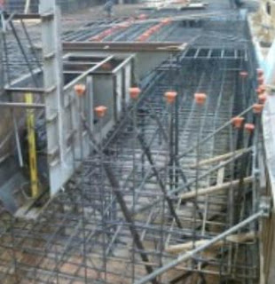
excavation protection for raft foundation slab with steel arragement
If the bearing area exceeds the above defined area, the projection may be changed and depending on the eccentricity due to lateral load moment and unsymmetrical axial loads on column and shear wall the symmetry of projection may be changed. The excavation is done around the area defined above to designed depth and necessary protections are taken to excavation related hazard and to give safety to neighbor buildings.
steel arrangement for inverted beam in raft foundation slab
The excavated area is well consolidated and if required necessary treatment is applied to soil to achieve desired bearing capacity depending on soil investigation data. The consolidated and treated surface is the base upon which raft slab will cast. In case of inverted foundation beams (both main and secondary beams) as discussed in previous post, the beams are cast after the slab with necessary precaution to provide construction joints. Further continuation is commenced after the proper curing of the raft slab and beams.

Pile Cap Analysis and Design Program from S.E Software

Pile Cap Analysis and Design is a design program that facilitates a foundation engineer to design to design and analysis a cap for Pile group. This is a windows-based and interactive design program of which professional version allows one to arrange piles in positions that align piles accurately or nearly close to provide center of resistance to center load in same axis to avoid eccentricity. This facilitates engineers to read the new position of pile coordinates from this program and to supply piles and pile caps layout to the contractor. This facility followed by the designing the cap at the same time. One can delete and/or add and even he can temporarily disable the influence of any pile in a cap. Manual calculation to input coordinates is not required as the arrangement of piles are pre-programmed. Caps for upto 16 piles in group having various sizes, shape and of different materials like steel, concrete or timber of any capacity can be handled and designed. Just provide number of piles and the pile cap edge with piles in standard layout are drawn. The dropdown menus provide facility to change spacing, concrete strength, edge distance, covering, grout strength, reinforcement, column size and many other relevant parameters.
Pile cap analysis and design program from S.E Software
Besides providing number of piles and layout, it can be calculated the number of piles and necessary alignment from provided axial loads. A cap can be designed for calculated reaction or for maximum capacity of pile. There have either option of entering cap thickness and then check it or calculation of required thickness for pre-defined or pre-programmed alignment/arrangement of piles. Once user has created drawing of pile groups and position of columns and cap edge, he can enter the design loads and the cap can be checked for service condition.

What is Piling? What is Point of Refusal?

Piling is portion of system of foundation that is pushed into just under the cap into the earth to provide support to the superstructure above. Piling is used in relatively weak shallow strata of the earth where loads from superstructure are transferred through piles to deeper stronger strata. It is often used as foundation repair solution for existing distressed building where foundation sinking, cracking and warping in different structural member are visible, alarming the dwellers of structural failure. The names that are used regarding piles depending on types and uses of them in Geotechnical engineers are :

a. Segmented piling


b. Push piling

c. Pile blocks

d. Steel piling 


Driving pile to point of refusal
e. Concrete piling

f. Double piling

There have other name like grouted pile and drilled pile and different languages and regions of the world also named piles in hundred ways.

In case of piling in sandy soils, friction developed around surface of the piles developed main capacity to the piles. In case of piling in clay soil, the capacity of piles are expected to develop from both wall friction between soil and pile surface and
capacity that developed at the tip of pile (end bearing) in a more stable or competent stratum.

Pile Point of Refusal:

This is a point at which level piling operation can no longer be continued into the earth without lifting or breaking the structure above. A lighter structure, as it has less weight, it reaches point of refusal at a relatively shallow depth. A heavy structure, as it is relatively heavier, it attains its refusal point at relatively deeper point so that it reach hard strata or rocks or it have combined or isolated action of   skin friction enough to support heavier loads. It should be noticed that a point of refusal in wet condition is not the same as it in dry condition.

Expansive Soil Instability of Foundation and Solutions to Avoid Foundation Repair in California

In residential building having relatively lighter structures expansive clay soils cause adverse impact on foundation resulting instability of foundation and foundation repair in this state is very common which involves a lots of money i.e., financial loss to the home owners. So home foundation problem, home foundation settlement or home foundation repair are very common terms in this state to both home owners and foundation repair contractors. Various contractors have made colorful pages in the web seeking quotes and tempting the home owners to inspect their foundations for free.


In the previous posts regarding black cotton soil as well as expansive soils it was discussed many times how expansive soil results failure or settlement to foundations. In this post we discuss possible solution more accurately simple and low cost solution for foundation problems of this type.

Solution for foundation problem:
Sign of home foundation settlement requiring foundation repair

In many places of the world, the home owners consider soil investigation for their small homes is not important. But the main fact is that expansive soil is harmful to the lighter structures having shallow foundation. The established and skill soil investigation firms should be chosen for this purpose. The soil investigation data assist foundation engineers to predict size and depth of foundation (if possible) avoiding top expansive layer if there any. If foundation have to found on expansive soil i.e., there is no way to avoid it, the investigation report provides information to design the foundation to withstand adverse effect of existing expansive soil. This also helps tp provide future maintenance facility if there have any problem.

For structures that are already affected by expansive soils, some foundation solutions are used to strengthen foundation to support foundation and to restrict further movement. This purpose can be served by various methods of underpinning and reinforcing the foundation walls. Underpinning prevents sliding and vertical movement and the later one are used to withstand lateral pressure.

The structures that exist on expansive soil and not yet suffer any adverse effects of expansive soil, soil maintenance is the cheapest and important solution to keep foundation safe. Soil maintenance includes providing and keeping constant and uniform moisture level in the soil. Maintaining uniform and continuous moisture to the soil prevent shrinkage and swelling of such soil. To avoid differential or localized or isolated saturation of soil proper drainage facilities should provide.

Problem with Pier and Beam Foundation in Texas

Expansive and reactive clay soils generate main foundation problems to lighter residential buildings in all over the world. United States are not an exception in this regard. In Texas, Virginia, California and some portion of Colorado, in United States, this problem is considered the main foundation problem and the home owners kept always busy to find the perfect foundation repair contractor to fix and repair their sweet home.

Texas foundation, foundation settlement

More than 90% of the older homes in Texas were built with pier and beam foundations. Heavy rainfall is very common in Texas especially in northern and eastern portion of Texas State. The excessive rainfall associates the foundation problems in pier and beam houses.

pier and beam foundation The foundation problems include development of cracks in walls and jamming of doors and windows. More over the older homes have no proper drainage to drain water and results accumulation of water or seepage of water towards vertical and lateral directions. The condition becomes worse where expansive clay soil exist beneath building which is very common in Texas. Expansive soil gets expanded with the presence of water and results the piers to heave. When  the clay soil under a pier gets saturated, this pier sunk as soil lacks its ability to support this pier.

Besides this major foundation problem sometimes termite damage, warped beams, decomposed wood in different structural members also make busy home owners to get repaired their foundations.

Black Cotton Soil

The property of volumetric changes with the change of atmospheric conditions makes black cotton soil dangerous to be founded buildings. It swells excessively when wet and shrinks excessively when dry resulting terrible cracks in soil without any warning. It has a great affinity to water. This tendency of soil is on account of the presence of fine clay particles. Cracks are formed due to movement of the ground on account of alternate swelling and shrinkage. The cracks thus formed are sometimes 15 to 20 cm wide and 2.5 to 4 m deep. The summary for all posts on black cotton soil are listed below:

Micropile: The Most Common Foundation Solution in Texas

The most common foundation problem are settlement of foundation and basement leak which is visible and sometimes leads to total foundation damage. The foundation repair is very critical, expensive and time consuming task. Sometimes it is almost impossible to repair a particular foundation. So it is very important to select a right foundation or foundation system.

Pile or pile group is a deep foundation that carry load to firm strata beneath foundation. But when a firm stratum lays at a relatively shallow depth but shallow foundation at this depth is not economical and for foundation repair task like retrofitting and underpinning structure micropile technique are adopted.


Micropile is a reinforced replacement pile that is installed by drilling followed by grouting. Typically micropile is designed to be small diameter having dia of less than 300 mm. It can be designed to act like conventional pile to withstand lateral and axial loading or it can be grouped to have combined soil and pile bearing action to support designed loading.

Micropile can be designed as a group of micropiles that the loads directly or closely spaced grids of micropiles of to reinforce the soil mass internally. In the later case they together with the soil form a reinforced composite that supports entire designed loads. In the first case the reinforcement in pile resist almost entire loads. In this post we discuss the fist methods of micropiling of directly loaded.

These piles can be designed as a substitute of conventional piles of medium to large dia to transfer load to relatively stable or firm strata. The loads that come from either axial or lateral sources are supported geotechnically by grout for each pile and structurally by reinforcement in pile. At least 90 percent projects of foundation construction and foundation repair in Texas involve this type of micropiles.

What are Cement Substitutes in Concrete Mix?

The materials which are used in concrete mix to improve some properties such as longevity and strength substituting cement to some degree are called cement substitutes. The reason for use cement substitutes are as follows:

a. Cement substitutes are used to replace cement which generates green house gas in its production process.

b. Cement substitutes provides a way for reusing of byproducts from different industrial processes like slag and many others.

c. The materials used as cement substitutes conserve energy as compared to cement as they require less energy for repurposing.

slag cement from ruby and scan cement of HeidelbergCement Group
Slag cement from ruby and scan cement of Heidelberg Cement Group
d. And at last environmental advantages are achieved using cement substitutes.

e. The materials used as cement substitutes conserve energy as compared to cement as they require less energy for repurposing.
Microsilica concrete with steel fibre reinforcement

f. And at last environmental advantages are achieved using cement substitutes.

The scenario of United States is, it imports 20% of national cement requirement. Thus the use of cement substitutes saves economy and energy to a great deal.

Cement substitutes are generally suggested to use in large scale projects than a small residential construction project as most of the contractors are not familiar with cement substitutes and special care are required to use these.

Thee important things to be keep in mind that the cement substitutes are not aggregate substitutes and additives. The example can make clear say, ground scrap rubber, concrete additives (like air-entrainment agent or plasticizer), ground glass are not cement substitutes.

The most common cement substitutes are:

a. Silica fume or microsilica
b. Flyash
c. Slag

Function of cement substitutes in concrete:

The use of slag or class F flyash can control alkali-silica reaction. Cement substitutes render less permeable concrete and give protection to the reinforcing steel against corrosion. The use of slag as cement substitutes of cement can limit sulfate attack from waste water and sea water.

What is adjustable steel column?

Adjustable steel column is a steel post that is designed to connect mechanically to roof to support it. The post supports a system of beams to provide additional stiffness that are required to withstand earthquake, wind loads or other sources of lateral displacement loads. The posts are usually hollow and an adjustable mechanism is attached to each post through providing threads. The adjustable system facilitates to adjust the column height when required. 

These columns are normally provided in basement. This column can be assembled as a single-piece or multiple-parts depending on the manufacturer’s production sizes and facilities. 
Adjustable steel column
Some requirements for adjustable steel columns according to International Residential Code (IRC):

1. The post diameter should not be less than 75 mm irrespective of structural design to support the loads. Both structural design and IRC minimum requirement have to satisfy in determining post diameter.
adjustable steel column
The post must be protected by corrosion-inhibitive paint. The both outer and inner surfaces of steel column have to paint with corrosion-inhibitive paint. If steel is treated with corrosion resistant coating or corrosion-resistant steel are used this requirement does not bear any importance.

Alteration of groundwater table: Impacts on foundation

We everyone know the term buoyant effect of water. This phenomenon is important in ground condition alteration. It is evident that intergranular pressure is increased with the removing of buoyant effect of water. This can be achieved by lowering the water table. In many practical cases this is not feasible or sometimes it is used as temporary solution. If somehow ground water table are altered, the immediate increase in intergranular pressure is obtained by 

γw x zw

Where zw is the change in ground water elevation.

foundation Settlement Damage due to ground water table raise resulting from Broken Water Main    Now think that water table alteration is possible, feasible and effective. Then another problem arises with alteration limit avoiding adjacent property. The water table cannot be altered exactly within the limits of desired property. Thus the change in effective pressure also occurs beneath adjacent properties of which foundation are designed considering existing ground water condition. The resulting impacts are cracked pavement or floor as well as cracked building.

It is worth mentioning that ground water table can be raised producing the same problem of adverse impact on adjacent properties and requires careful understanding about the impact before achieving the raising.

Thus any alteration of ground water table results some kind and degree of effect on the environment. So it is necessary to take permission from the local environmental authorities to adopt such action.

How are Foundations Installed Displacing Soil?

Foundations are generally installed below ground surface from the view of geotechnical and environmental considerations. Foundation depth should be designed such that it remains below:

1. Organic top soil

2. Muck or peat

3. Unconsolidated materials like garbage bumps or sanitary landfill etc.

4. Freezing thawing influencing depth

5. And below other soils that are influenced highly with the moisture fluctuation like expansive black cotton soil

In the previous couple of posts I have discussed many problems of foundation on black cotton soil  as   well   other  expansive soil  and  also  their  remedies  and distribution of such soils in united states and India. In this post I shall discuss displaced soil effects. 
Basement slab are drilled and footing-column are installed which is followed by the backfilling to ground surface
As foundations are placed below ground level, it displace some soil mass. When spread footing are used the displaced amount are summation of the footing weight and the column that rested on footing. Where basement is required for parking facilities, the basement slab is generally rested on top of the footing pad directly. Sometimes holes are excavated through the slab to provide footing and column and then the holes are backfilled to the ground surface. 

If the unit weight of the soil=γs
 
And unit weight of concrete= γc
Column reaction=P
Allowable bearing pressure=qa
Footing depth=D
Thickness of footing=Dc
Then existing pressure before excavation and foundation installation
= γsxD
Now induced soil pressure increment due to column reaction,p=P/B2 = q1
Pressure increment due to displace soil=( γc- γs) xDc= q2
mat foundation served as basement displacing soil
Net increment of pressure= qn =q1 +q2 ≤qa


In case of steel columns to avoid corrosion concrete pedestals is provided up to ground and in case of concrete columns, at the footing level it is attached to footing with dowels.

spread footing with basement displacing soil with necessary drainage facility
If the floor slab is rested directly on ground, careful selection of backfill soil and compaction method is required. The backfill soil that is placed around the basement wall should have free draining property and where required a perimeter drainage system is installed to control hydrostatic pressure.

What is admixture? How it Works?

Admixtures are a mix of several chemicals or single chemical that are added to mortar, concrete or grout during mixing or in wet condition just after mixing or even after hardened mix to have a concrete of desired of properties apart from natural concrete.

There have some standard that are used to define and evaluating the quality of admixture. New European Standard EN 934 was developed in 2002 which covers almost all type of admixture. The current part 2, out of recently developed five parts, covers concrete.
Admixture Dispenser for ready mix concrete
Parts 1-3 of BS 5075 also deals with concrete admixture and BS 4887 covers admixture for mortars. ASTM C494 is the most precisely specified standard that are widely used in USA and many other countries of the world as a reference for defining, using and selection of admixture.

Mechanism of working admixtures follows one or more of the following actions:

• Chemical influence on the hydration process of cement, Changing the rate of stiffening either by accelerating or retarding the rate of chemical reaction in one or more cementing phase.

• Achieving better Admixture Dispenser for ready mix concretedispersion of particles producing adsorption on cement surfaces. This action results plasticizing or superplasticizing.

• Achieving increment of air entrainment by influencing the surface tension of water.

• Increasing mix cohesion or plastic viscosity influencing the water rheology.

• To introduce specific properties, like increasing corrosion protection of steel embedded with concrete or water repellence, using special chemical over the hardened surface of concrete.

Enlarged Tip Piles for Granular Soils

Enlargement of pile tip increase bearing capacity of pile. This technique is generally used in granular soils. This technique can be performed in several ways. One type of enlargement is achieved by driving a tube at the bottom with a concrete plug to the desired depth. When is added the concrete plug is forced out into the soil. After base is completed the tube is withdrawn. But this withdrawal continues while the concrete expands out at the tip of the tube. This process forms a cast-in-situ (CIS) concrete shaft.
Cast in place pile operation
Alternately, corrugated shell casing or a pipe is bottom-driven into the base and the tube withdrawn. This forms an annular space between pile and soil. This annular space either filled with granular filler material or else closes onto the shell. This piling work is then completed as a cast-in-place (CIP) concrete pile. In these either CIP or CIS piling techniques, the shaft is provided with steel reinforcement as requirement of the design that consider structural capacity of pile  (both axial capacity of pile and lateral capacity of pile).
Enlarged  Tip Piles for Granular Soils
In the above figure phase (1) to (3) depict the boring of gain desire depth and using expandable wings to make enlarge base and then concreting to fill the base. The phase (4) shows that the withdrawal of boring system and  the phase (5) shows lowering of cast in place pile to touch the base cast previously.
Enlarged  Tip cast in place Piles for Granular Soils
The another alternative are achieved by attaching to pile shaft a reinforced concrete base having shape like a frustum of a cone. This is very common to use a corrugated shell shaft or a pipe having thin-wall and enlarged tip base being mandrel driven to bear in generally granular subsoils. As a cast-in-place pile the shaft is completed and steel reinforcement is provided as explained earlier. Enlarge-tip base in the above explained precast form can be used with solid shafts like timber piles and it can be of sizes of wide range.

Automatic Vicat Apparatus for Determination of Setting time of Cement

Cement is the bonding component of concrete which binds the inert filler materials of concrete mass. In this post we will discuss about Vicat Apparatus which is a simple equipment for testing cement. Everyone in civil engineering specially in material engineering are known about this equipment. So why this Apparatus are in discussion this is the question. we will discuss a automated apparatus manufactured by Geotechnical Testing Equipment.


The Automatic Vicat Apparatus is designed and manufactured using the most recent and sophisticated technology, it is used for the initial  and final setting time determination of cements or mortar pastes. The apparatus is manufactured with anticorrosion components to be used in places with humidity up to 90% and 20°C. 
Automatic Vicat Apparatus for setting time determination of cement
The entire test is made in a fully automatic way and gives a very precise and repeatable result with controlled temperature as required by EN Specifications.

The results are printed on the incorporated printer and this eliminates the manual operations of installing and zeroing the paper graph on the drum.

The use of the appliance is extremely simplified by the guiding menu that is available in different languages.

CM 0123 


Automatic Vicat Apparatus Complete with EN and ASTM Initial and Final needles, Consistency Plunger, 1 x EN and ASTM Mould and Glass Plate. 

Black Cotton Soil of Deccan Lava Plateau

In India Black cotton soil spread over Maharashtra, western parts of Madhya Pradesh, parts of Andhra Pradesh, parts of Gujarat, some parts of Tamil Nadu and Deccan Lava Plateau. Among these the black cotton soils of Deccan Lava Plateau are discussed here. 
Most of black-cotton soils of India are spread across the Deccan Lava Plateau, the Malwa Plateau, and interior Gujarat, where there is both moderate rainfall and underlying basaltic rock. Because of their high clay content, black soils develop wide cracks during the dry season, but their iron-rich granular structure makes them resistant to wind and water erosion. They are also highly moisture-retentive, thus responding well to irrigation.
Expansive soil Black cotton soil of Deccan plateau india
The soil in the Deccan plateau is made up of black basalt soil. This type of soil is rich in humus. In addition to iron content they contain fairly high quantities of lime, magnesia and alumina.
Map of Deccan plateau which is enriched with black cotton soil
Such texture and composition of soil are formed due to volcanic action of Deccan region. These igneous rocks break down in to the black soils rendering fertility to them. They commonly known as the black cotton soil because it is best suited for the cultivation of cotton.
Columnar basalt soil of Deccan Traps

What is Anchor Bolt?

The factored base shear in column, in normal loading conditions, is resisted by friction between plate and support of it. The introduction of anchor bolts is to provide addition capacity against shear that may occur due to many unfavorable conditions.

Function of anchor bolts:

1.To stabilize column preventing uplift induced by moments that generated by lateral load(earthquake and wind) or any other sources.

2.  To keep the column in position during erection process.

Steel anchor bolt having threaded rod’s with nutsTypes of Anchore bolt:

a. Drilled-in bolts 

b. Cast-inplace bolts

The application of these types of anchor bolts are :

a. Drilled-in bolts

Drilled-in anchor bolts are not frequently used. In this process bolts are installed after the concrete is set.

b. Cast-inplace bolts

Cast-inplace anchor bolts are placed before setting of concrete. This ancor bolt may be bolts, threaded rods having nuts or hooked bars.

Hooked bars:
Among these anchor bolts the hooked bars are suitable for base plates that are loaded axially.
-
Bolts:
Bolts can be used either to anchor base plate subjected to moments or to anchor axially loaded base plate.
steel hooked bars anchor bolt
Threaded rod’s:
Drilled steel anchor bolts filled with epoxy
Both axially loaded base plates and base plates subjected to moments and be anchored by threaded rod’s with nuts. This system of anchoring are required when the size and length obtained from design calculation for the specific design exceed those of standard size bolts. This threaded nut system fails when stress in the rod is reached to tensile capacities.

How to Determine Structural Shaft Resistance of Micropile?

The internal capacity of a micropile frequently governs its overall design, because of its small cross sectional area and the large resistance provided by the grout/ground bond due to the construction techniques.

The reinforcement steel is the element that carries most of the load. However the load is resisted by both the steel and the grout. It is important to take into account this composite action to optimize the internal pile design. The use of steel pipe or casing as reinforcement elements has become more popular, especially when requiring minimal deflections or supporting lateral loads.

In practice, the design compressive stress in the steel reinforcements is limited to 50% of the yield strength. The pile capacity is normally derived from the allowable structural capacity of the reinforcements in the preliminary design.

 
Cement Grouting of Drilled MicropileOther components, such as the grout and additional reinforcement bars can be included to enhance the allowable structural capacity. However extra care is needed to ensure its effectiveness during construction.

The grout commonly consists of cement and water, with water-cement ratios between 0.40 and 0.55. The
minimum ratio is set by the requirement that the grout should be fluid enough to allow efficient pumping and injection. The maximum ratio is imposed results because an excessive amount of water would cause bleeding, low strength, increased shrinkage and poor durability. Fine sands can be added to the mix to reduce costs. Sand cement ratios are limited to 3, but they rarely exceed 1.5. Admixtures are added to modify grout properties: prevent shrinkage, reduce water content, maintain pumpability, accelerate or retard setting, and, prevent bleeding.

Defective Piles and Corrective Measures

In previous posts we discussed about defective piles. Now we discuss what to do for defective pile. Defective pile associated with injurious splitting, steel deformation, brooming and splintering of wood, or concrete spalling and crushing. A pile which is not positioned properly will not be allowed to repositioning applying forces or other mechanism. The contractors are responsible for corrective measures for defective pile at their own expanses including coercions of driving pile below the designed cut-off level, wrong positioning of piles and damaging of pile due to  improper  or  wrong driving. The following methods are used to for correction of defective piles:

(a) The piles shall be withdrawn and replaced by new and, if necessary, longer piles, or

(b) Replacement piles shall be driven adjacent to defective or low piles, or

Naked steel tie of defective pile due to mud inclusion during concreting
(c) The piles shall be spliced or built up, as otherwise provided herein, or a sufficient portion of the footing extended to properly embed the piles. Timber piles shall not be spliced without specific permission of the Consultant. All piles, pushed up by the driving of adjacent piles or by any other cause, shall be driven down again.
Defective pile: Irregular Pile Sections with Vertical Discontinuities
In case of application of hammer of grater energy to obtain required penetration and for achievement of designed bearing capacity, as accepted by the consultant, the contractor cannot claim extra work.

Followers