Foundation, Concrete and Earthquake Engineering

Molecular Sandwich of Black Cotton Soil

The expansion potential of Black cotton soil is the combined influence of clay particle type and its quantity in the soil. Clay particles which cause a soil to be expansive are extremely small. Their shape is determined by the arrangement of their constituent atoms which form thin clay crystals.


The principal elements in clay are silicone, aluminum and oxygen. Silicone atoms are positioned in the center of a pyramid structure called a tetrahedron with one oxygen atom occupying each of the four corners. Aluminum atoms are situated in the center of an octahedron with an oxygen atom occupying each of the eight corners.
Octahedral sheet is
sandwiched between two tetrahedral sheets to create the mineral structure of Black Cotton soil
Octahedral sheet is sandwiched between two tetrahedral sheets to create the mineral structure of Black Cotton soil
Because of electron sharing, the silicon tetrahedrons link together with one another to form thin tetrahedral sheets. The aluminum octahedrons also link together to form octahedral sheets. The actual clay crystals are a composite of aluminum and silicon sheets which are held together by intra-molecular forces.
Silicon
Tetrahedral sheets are formed sharing electron in Black Cotton Soil
Silicon Tetrahedral sheets are formed sharing electron in Black Cotton Soil

There are many other elements which can become incorporated into the clay mineral structure Black cotton soil such as hydrogen, sodium, calcium, magnesium, sulfur, etc. The presence and abundance of various dissolved elements or “ions” can impact the composition and behavior of the clay minerals.
Aluminum
octahedral sheets are formed sharing electron in Black Cotton Soil
Aluminum octahedral sheets are formed sharing electron in Black Cotton Soil
One octahedral sheet is sandwiched between two tetrahedral sheets to create the mineral structure. In Black cotton soil, groupings of the constituent clay crystals will attract and hold water molecules between their crystalline sheets in a sort of “molecular sandwich”.

Adsorption and Black Cotton Soil

Water molecules consist of two hydrogen atoms sharing electrons with a single oxygen atom. The water molecule is electrically balanced but within the molecule, the offsetting charges are not evenly distributed. The two positively charged hydrogen atoms are grouped together on one side of the larger oxygen atom. The result is that the water molecule itself is an electrical “dipole”, having a positive charge where the two hydrogen atoms are situated and a negative charge on the opposite or bare oxygen side of the molecule.

The electrical structure of water molecules enable them to interact with other charged particles. The mechanism by which water molecules become attached to the microscopic clay crystals of black cotton soil is called “adsorption”. Because of their shape, composition and resulting electrical charge, the thin clay crystals or “sheets” have an electro-chemical attraction for the water dipoles. The clay mineral “montmorillonite”, which is the most notorious and rich component of black cotton soil, can adsorb very large amounts of water molecules between its crystalline sheets and therefore has a large shrink-swell potential.
Dipolarity of Water Bonds
Dipolarity of Water Bonds 
When potentially expansive soil becomes saturated, more and more water dipoles are gathered between the crystalline clay sheets, causing the bulk volume of the soil to increase or swell. The incorporation of the water into the chemical structure of the clay will also cause a reduction in the capacity or strength of the soil. 
Black Cotton Soil in Shrinkage
During periods when the moisture in the expansive soil is being removed, either by gravitational forces or by evaporation, the water between the clay sheets is released, causing the overall volume of the soil to decrease or shrink. As the moisture is removed from the soil, the shrinking soil can develop gross features such as voids or desiccation crack. These shrinkage cracks can be readily observed on the surface of bare soils and provide an important indication of expansive black cotton soil activity at the property.

Historic Seismicity of Bangladesh


------------------------------------------------------------------------------------- -------------------------------------------------------------------------------------

Historic Seismicity Map of Bangladesh

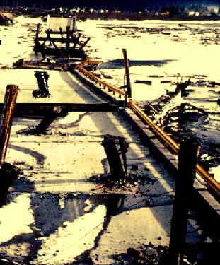
1964 Alaska Earthquake: Lateral Spreads Damaged 200 Bridges

During the 1964 Alaska earthquake, more than 200 bridges were damaged or destroyed by spreading of floodplain deposits toward river channels. The spreading compressed the superstructures, buckled decks, thrust stringers over abutments, and shifted and tilled abutments and piers.


This news are known to all but do we know what is lateral spreading or what is the relation between earthquake and lateral spreading. Let us try to find out the answer of above questions.
In Alaska Earthquake March 27, 1964, Twentymile River Bridge fell into
the river, and some of the wood piles were driven through the reinforced
concrete deck
In Alaska Earthquake March 27, 1964, Twentymile River Bridge fell into the river, and some of the wood piles were driven through the reinforced concrete deck.

Lateral spreads involve lateral displacement of large, surficial blocks of soil as a result of liquefaction of a subsurface layer. Displacement occurs in response to combination of gravitational forces and inertial forces generated by an earthquake. Lateral spreads generally develop on gentle slopes (most commonly less than 3 degrees) and move toward a free face such as an incised river channel. Horizontal displacements commonly range up to several meters, but where slopes are particularly favorable and ground shaking durations are long, displacements may range up to several tens of meters. The displaced ground usually breaks up internally, causing fissures, scarps, horsts, and grabens to form on the failure surface.

Failure of Million Dollar Bridge on the Copper River Highway in 1964 Alaska
Failure of Million Dollar Bridge on the Copper River Highway in 1964 Alaska Earthquake
 Lateral spreads commonly disrupt foundations of buildings built on or across the failure, sever pipelines and other utilities in the failure mass, and compress or buckle engineering structures such as bridges founded on the toe of the failure. Damage caused by lateral spreads, though seldom catastrophic, is severely disruptive and often pervasive.

LIQUEFACTION AND GROUND FAILURE

In liquefaction process soil deposits behave as a viscous liquid rather than as a solid temporarily losing strength. Cohesionless soil deposits primarily sands and silts under seismic waves, primarily shear waves that pass through saturated granular layers, distort the granular structure, and cause loosely packed groups of particles to collapse. Disruptions to the particulate structure generated by these collapses cause transfer of load from grain-to-grain contacts in the soil to the interstitial pore water. This transfer of load increases pressure, in the pore water, causing drainage to occur. If drainage is restricted, a transient build up of pore-water pressure will occur. If the pore-water pressure rises to a level approaching the overburden pressure grain-to-grain contact stresses approach zero and the granular layer temporarily behaves as a viscous liquid rather than as a solid and liquefaction has occurred. In the liquefied condition, soil deformation: may occur with little shear resistance. Deformations large enough to cause damage to constructed works (usually more than 0.1 m) are called ground failure.
Liquefaction of sediments beneath the road  caused by magnitude 7.3 Hebgen Lake earthquake
Looseness of the soil, the packing arrangement of soil grains, the amount of cementing between particles, and the amount of drainage restriction are factors that control the degree of liquefaction.
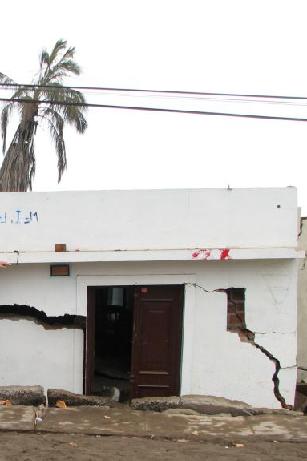
Building settled about 1 m due to liquefaction in 2007 Peru Earthquake
The amount of soil deformation following liquefaction depends on the looseness of the material, the thickness and areal extent of the liquefied layer, the ground slope, and the distribution of loads applied by buildings and other structures on the ground surface.

Determination Difficulties of Cyclic Strains of Soil During Earthquake

Estimation of the seismic response of shallow foundations during a strong earthquake has been proven a difficult task throughout the years. The main cause of this difficulty arises from the fact that soil behaves in a highly non-linear manner when subjected to large cyclic strains. 


It can deform substantially and, when saturated, can develop high pore pressures and finally liquefy. Liquefaction consequently leads to severe loss of bearing capacity, which damages seriously the superstructure. Extensive damage  to  shallow  foundations  due  to  liquefaction  has  been  reported  in numerous cases in the past, from Niigata (1964) earthquake to the more recent 1999 M 7.4 Kocaeli earthquake. 
 

Road Surface Subsided Inequally Due to Liquefaction in Nanokamachi TownDespite the severity of damages, relatively little has been achieved towards the development of a consistent methodology for the design of foundations systems under these circumstances. Usually, the presence of superstructure is neglected and calculations are performed for free-field conditions. 
 
Road Surface Subsidence  in Ojiya City  
Liquefaction Impact
Liquefaction Impact 
The onset of liquefaction is evaluated and empirical correlations for settlements, developed for free-field conditions, are used. However, the presence of superstructure differentiates significantly the response from that under free-field conditions, so that such methods prove too approximate.
Apartment Houses  Leaned in Niigata, Japan during  magnitude 7.4  Niigata, Japan  Earthquake 1964

Kaptai Dam of Bangladesh

Kaptai dam is the one and only dam of Bangladesh that is used to generate hydro-electric power. This dam was constructed across Karnaphuli River at Kaptai in Rangamati district, 65 km upstream of Chittagong. It is an earthfill embankment dam which reservoir is called Kaptai Lake. The water storage capacity of the Kaptai dam is 11000 km2. The construction of the dam was started in 1957 and was completed in 1962.

Under the guidance of then Chief Engineer (Irrigation) Khwaja Azimuddin, the construction site was chosen at present location of the dam in 1951. The International Engineering Co. Inc. (IECO) was engaged for a study on the project. Utah International Inc. was selected as construction contractor.
The 16 gated (each 12.2 m X 11.3 m size) spillway of Kaptai Dam have discharge capacity of 625000 cusec
The 16 gated (each 12.2 m X 11.3 m size) spillway of Kaptai Dam have discharge capacity of 625000 cusec.

In 1962, the the dam, spillway, penstock and two units of powerhouses were built. Each of the powerhouses was capable of generating 40MW of electricity. In November 1981 another 50MW generating unit was completed. In October 1988 the 4th and 5th generating units were installed which raised the total generation capacity to 230MW. The total cost of Unit 1, Unit 2 and a part of Unit 3 was Rs. 503 million and the total cost of extension was Tk. 1,900 million. The spillways was constructed on the left side of the main dam. The 16 gated (each 12.2 m X 11.3 m) spillway have discharge capacity of 625000 cusec. The construction of these system (dam, spillways and others) required to excavate 113400 cubic m. The dead storage at 23.16m above MSL is 1.18 million ac-ft. Flood storage capacity is 0.83 million ac-ft.  
Kaptai Dam with spillway and Power Plant
Kaptai dam can reduce the downstream flood peak in the Karnafuli river by 50% by storing water in the reservoir. Kaptai dam is 670.56m long and 45.7m high. The width at the foundation level is 45.7m and at crest level 7.6m. The crest level is 36m above mean sea level (MSL).
Beauty of Kaptai Lake
 The 11000 km2 catchment area of the reservoir of the Kaptai dam claims 220 km2 of cultivable land of which 40% cultivable land in this area and displace 18000 families submerging a total of 655 km2

India Have Got Third Position in Dam Building

Before independence i.e. 1947, there were fewer than 300 large dams in India and by the year 2000 the number had grown to over 4000, more than half of them built between 1971 and 1989. India is declared to be the third in the world in dam building, after US and China. 

Dams in India have been built across many perennial rivers. These dams are a part of the several multi-purpose projects launched by India to serve a variety of needs. In a multi-purpose project, a river forms a unit and a river valley is developed, by exploiting all the resources of the river. 
Durgapur Barrage across the Damodar River at Durgapur in Bardhaman  district  in  the 
Indian state of West Bengal.
Durgapur Barrage across the Damodar River at Durgapur in Bardhaman district in the Indian state of West Bengal.
Dams are built to harness the river water so that it can be utilised according to  needs. A multipurpose project is launched often for storing water for irrigation purposes, generating hydro-electricity by utilising the water stored by the dams, preventing floods and facilitating afforestation in the catchment areas of the reservoirs. However, the dams also provide drinking water, using the canals for navigation in some areas and also facilitating pisciculture and recreational activities. The main multipurpose projects constituting the major Indian dams are the Hirakud Project in Orissa, the Bhakra Nangal inPunjab, the Damodar Valley Project in Bihar and Bengal, the Tungabhadra Project in Andhra Pradesh and Karnataka, the Rihand Project in Uttar Pradesh.
Hirakud Dam across the Mahanadi River, about 15 km from Sambalpur in the state of Orissa in India.
Hirakud Dam across the Mahanadi River, about 15 km from Sambalpur in the state of Orissa in India.  
Some of the Indian dams were built primarily for flood control, water supply, and hydroelectric power generation, the primary purpose of most Indian dams (96 percent) remains irrigation. In fact, large dam construction in India has been the main form of investment in irrigation undertaken by the Indian government. But, starting in the 1980s, public investment in large dams in India has been the subject of a sustained controversy that was epitomized by the Sardar Sarovar Project, based on the balance between the social, environmental, and economic costs of dams and their benefits. 
Bhakra Nangal Dam is situated across the river Sutlej that falls under the region of Bilaspur in Himachal Pradesh
Tourist Spot near Dams is very much popular and good sources for attracting tourists. There are all the states in India where dams have been established but Karnataka is very rich in having most of dams and Reservoirs. Dams in Karnataka is very popular serving the purpose of people of Karnataka and Bangalore. Karnataka is much enriched in terms Dams in South India.

1. Almatti Dam
2. Gajanur Dam
3. Gundal Reservoir
4. Harangi Dam
5. Hidkal Dam
6. Kadra Dam
7. Kanakanala Dam
8. Kanva reservoir
9. Kodasalli Dam
10. Krishna Raja Sagara Dam
11. Lakkavalli Dam
12. Linganamakki Dam
13. Marconahally Dam
14. Mari Kanive Dam
15. Narihalla Dam
16. Nugu Reservoir
17. Sathanur Dam
18. Supa Dam
19. Suvarnavathi Reservoir
20. Thippagondanahalli Reservoir
21. Tunga Anicut Dam
22. Tungabhadra Dam
23. Vani Vilas Sagar Reservoir

Expansive Soils in United States

Soils which contain clay in rich proportions can be defined as elastic soil. They expands and contracts with the variation of moisture.As soils become saturated with water, the clay expands and loses strength. This condition allows the foundation to sink much the same as you would standing in wet mud.

Conversely, clay soils contract when moisture is taken away. Unfortunately the soils do not always loose moisture evenly, which allows one area to contract faster than another. The soils contract, the foundation loses needed support and therefore settles.

Reddish Clay Soil of South Carolina
Clay is the reddish soil that plagues the southeast. If you live in South Carolina, Georgia, or North Carolina, there's a high degree of likelihood your home sits on some amount of expansive soil. However, it's important to watch for the signs of foundation failure to see if your home is suffering as a result of poor soil.
Foundation Failure Due to Expansive Soil

Farakka Barrage: A curse to Bangladesh and Blessing to West Bengal

West Bengal is the rice bowl of India and water required for irrigation and other purposes are supplied via Ganges River. To control the flow and to protect port Kolkata (Calcutta) against siltation in 1961 Indian government decided to construct Farakka Barrage across Ganges River. 


Farakka barrage was constructed by Hindustan Construction Company. It has 123 gates and it serves water to the Farakka Super Thermal Power Station. There are also sixty canals which can divert the water to another place.
Farakka Barrage
Farakka Barrage
Farakka barrage was built to divert up to 40,000 cu ft/s (1,100 m3/s) of water from the Ganges River into the Hooghly River during the dry season, from January to June, in order to flush out the accumulating silt which in the 1950s and 1960s was a problem at the Port of Kolkata (Calcutta) on the Hooghly River. The Hooghly River divides Murshidabad and Malda districts of West Bengal. 

Farakka Barrage is located in the Indian state of West Bengal, roughly 16.5 kilometres (10.3 mi) from the border with Bangladesh near Chapai Nawabganj District. Construction was completed in 1975.

Farakka Feeder Canal to  Bhagirathi-Hooghly
Farakka Feeder Canal to Bhagirathi-Hooghly
Operations began on April 21, 1975. Farakka barrage is about 2,240 metres (7,350 ft) long. The feeder canal from the barrage to the Bhagirathi-Hooghly River is about 25 miles (40 km) long.

The surrounding area of ‘The Farakka Water Barrier' becomes the desert as well as non-cultivating land. That means, a huge cultivable land of Bangladesh becomes non-cultivable land just because of ‘The Farakka Water Barrier'. Moreover, a good number of people of this arena, who lived near Farakka in the recent past, have migrated themselves in India.

Settlement Limitations of Foundation

Settlement limitation requirements in most cases control the pressure which can be applied to the soil by the footing. Acceptable limits for total downward settlement or heave are often 1 to 2 inches or less.


(1) Total Settlement. Total settlement should be limited to avoid damage with connections in structures to outside utilities, to maintain adequate drainage and serviceability, and to maintain adequate freeboard of embankments. A typical allowable settlement for structures is 1 inch.
Tie Beam or Grade Beam Cracks Associated with  foundation Settlement
Tie Beam or Grade Beam Cracks Associated with foundation Settlement
(2) Differential Settlement. Differential settlement nearly always occurs with total settlement and must be limited to avoid cracking and other damage in structures. A typical allowable differential/span length ratio D/L for steel and concrete frame structures is 1/500 where D is the differential movement within span length L.

Indian Dams and Future of Bangladesh

The natural law of the flow of water is to flow upstream to downstream and Bangladesh is located downstream of many international river that originated in the country that surrounded her named India. We Bangladeshis are learned from very childhood that Bangladesh is criss-crossed by rivers. The control these flow and to protect these low land countries various international forums worked together and various international laws are established and they are also exercised with a great deal of authority. 


Internationally, it is very much well known that no upstream country can directly or indirectly control the natural flow of water. But the people of Bangladesh are having the reverse thing from the monster like country India. They are trying to diminish the ultimate existence of Bangladesh and they also think that all the fools are live in Bangladesh and all the natural talents are live in India.In the international  media, they say that they are the well wisher of Bangladesh but their attitude tells the reverse one. They do not show any kind of respect whenever they talk to us and their ambassadorial correspondence with us is very much influencing with no compromising attitude.
Farakka Barrage across the Ganges River
Farakka Barrage is a barrage across the Ganges River, located in the Indian state of West Bengal, roughly 10 kilometres (6.2 mi) from the border with Bangladesh. Construction was started in 1960 and completed in 1974.
We, the people of Bangladesh, have got the ultimate bad experience from the ‘Farakka incident'. The result of the ‘Farakka water barrier' is very bad. The surrounding area of ‘The Farakka Water Barrier' becomes the desert as well as non-cultivating land. That means, a huge cultivable land of our country becomes non-cultivable land just because of ‘The Farakka Water Barrier'. Moreover, a good number of people of this arena, who lived near Farakka in the recent past, have migrated themselves in India.
Farakka Barrage the Sorrow of Bangladesh
The latest water control system of India is known as ‘Tipaimukh Water barrier' and they (India) are saying that they are trying to build this barrage to produce electricity as their arguments against this barrage. The interesting thing is, their own people are against their decision and the people of Monipur are providing the leading. The bad things that will happen in our country just because of the barrage are listed below: 


- The north-west part of our country will be desert as well as non-cultivable land. 

- About 25-30 rivers, sub rivers will dry up just because of the barrage. 

- About 30 millions people will be affected and they will be bound to migrate to other places or even other countries. 

- The weather of the country will be wormed up. 

-The green of the north-west region of our country will be destroyed

Technical Purposes of the Tipaimukh Dam

The basic purpose are:

1. flood control and 

2. hydropower generation. 

The political purposes make the hydropower case prominent. Most of the inundation is in Manipur and Mizoram states, whereas it would moderate floods in lower Assam. To ensure fare share of benefits to those two states, hydropower generation is also taken into account. The states  in North-East are having severe power shortage over years (peak shortage upto  25% in Arunachal).    Once   Arunachal   starts  producing hydroelectricity from giant Subansiri projects, the North-East India will become energy sufficient. On the other hand, there are no alternative to dams for flood-control of a rainfed river. Incidentally, both flood-control and hydropower generation reservoirs work in similar way – they retain water during Monsoon and release more during lean season, i.e. reservoir is filled up during rainy season and used up in dry season.
Indian Flood Zone Map
The Barak valley, consisting of three of the forty highly flood prone districts in India, goes under water three to four times (2002, 2004, 2007) in a decade. In 1995, plan for flood control Dam in Tipaimukh and reactions in Bangladesh were reported. Very often Barak flood is more devastating than that of Brahamaputra. A detailed assesment (2007 flood report) of floods in Assam can be found here. It has long been alleged that North-East has been neglected in terms of development and lack of flood control is one of the evidences.

The Tipaimukh dam is planned to produce 450MW in lean season and 1500MW in peak. All three states would have 12% share of the electricity and rest would go to the North East grid.

Vinyl Sheet Pilings for Cost-Effective Construction

The construction industry has all along been a booming industry with a lot of innovations taking place all the time. Nowadays, we see a lot of vinyl sheet piling system used as an alternative to hardwood and steel sheet piling. Vinyl has its own advantages as it is extremely durable, cost effective and weather resistant. Furthermore, vinyl will not be affected by rodents, or salt or fresh water and it is environment friendly. All these positive features make vinyl ideal material for sheet pilings.

Vinyl sheet piling has been gaining popularity in the construction market in recent times. Vinyl has become the preferred choice of engineers and contractors who use it for bulkheading and seawalls. Now with more and more attention being paid to vinyl, some suppliers have created the biggest vinyl box profile in the world allowing for even better benefits for contractors and engineers. 

Sheet Piles for Cut Off Wall
Cutoff walls call for extreme precaution. It is essential to contain hazardous materials to prevent seepage into ground water. Flood control structures are equally important as life and property need to be safeguarded from violent storms. While no product can provide 100 percent guarantee to hold up against a storm, advanced vinyl decking material may provide a better chance of survival.

A new vinyl sheet pile section is now being manufactured to serve the marine and civil industries. They are expected to offer more effective performance in cutoff, flood control, bulkhead and seawall applications.


Vinyl sheet pilings reduce seepage through the interlocks, allowing minimal use of sealants. Vinyl sheets can be installed at all places where steel sheet piling can, with the use of proper equipment. The light weight, durability and low cost of vinyl sheet piling make it a viable cost effective solution for projects all over the world.

It needs to be noted that vinyl is an inert material and hence does not dissolve when it comes into contact with many frequently occurring chemicals. Besides, no poisonous substances are released into the ground or the water.

A sheet piling was hitherto made of metal and wood but the scenario has changed with more and more people opting for vinyl sheet pilings for its many advantages including low price.
The components of a vinyl seawall are manufactured conforming to some very rigid standards without giving room for errors and the advantage is vinyl does not fade like wood.

The rampant use of vinyl sheet piling all over has made other traditional materials like wood, steel, concrete, and aluminum outdated. Traditional materials had all along lacked performance guaranteed as they were found breaking down almost immediately in a salt-water environment. The reason people are choosing vinyl sheet piling is that it is lot more cost effective than the type of materials used earlier.

As a family owned and operated company, Gulf Coast Treated Piling and Timbers has been manufacturing and supplying high quality building materials including vinyl sheet pilings nationwide for over 35 years. 

IBC Requirements for Slab-on-Ground Foundations on Black Cotton Soil

Moments, shears and deflections for use in designing slab-on-ground, mat or raft foundations on black Cotton Soils shall be determined in accordance with WRI/CRSI Design of Slab-on-Ground Foundations or PTI Standard Requirements for Analysis of Shallow Concrete Foundations on black Cotton Soils. 

Using the moments, shears and deflections determined above, nonprestressed slabs-on-ground, mat or raft foundations on black Cotton Soils shall be designed in accordance with WRI/CRSI

Design of Slab-on-Ground Foundations and post-tensioned slab-on-ground, mat or raft foundations on black Cotton Soils shall be designed in accordance with PTI Standard Requirements for Design of Shallow Post-Tensioned Concrete Foundations on black Cotton Soils.


Post tensioning Slab on Grade
It shall be permitted to analyze and design such slabs by other methods that account for soil-structure interaction, the deformed shape of the soil support, the plate or stiffened plate action of the slab as well as both center lift and edge lift conditions. Such alternative methods shall be rational and the basis for all aspects and parameters of the method shall be available for peer review.

Concrete admixtures/additives:water reducers

Concrete plasticizers are the mainstream products for readymix facilities. They are widely used all over the world and for the moment they are the number 1 admixture/additive as far as it regards the worldwide consumption.

Others name used for this category of additives are:

- normal water reducers

- water reducing additives/admixtures

- normal plasticizers etc.

Water reducers for concretePlasticizers are mostly based on lignosulfonates. Lignosulfonates or sulfonated lignins are by - products of the paper industry, recovered from the pulping liquids.

Lignosulfonates are usually modified with special polymers to mainly control air entrainment and setting times, or improve/regulate other parameters.

Other chemicals used are hydroxycarboxylic salts.

Plasticizers are considered to give water reductions at the region of 10%. A little more or a little less.

Usual dosages are between 0.25 – 0.8% by cement weight.

Example: a concrete mix with 350Kg cement/m3 can accept a plasticizer quantity between 0.25 x 350/100 and 0.8x350/100 Kg/m3 or 0.875 – 2.8 Kg/m3.

The commonest dosages are in the range of 0.3-0.4% by cement weight.

For each different project, product trials should be made to conclude to an optimal dosage.

HOW DO PLASTICIZERS FUNCTION?

Cement particles tend to flocculate and the role of plasticizers/water reducers is to induce deflocculation.

This is achieved by adsorption of their active constituents onto the cement particles. Thus the surface charges on their surface are neutralized and the cement flocs break up.

By this way the water that was tied up in the cement flocs is released and used to reduce the viscosity of the mixture.


WHY ARE PLASTICIZERS USED?

Plasticizers are used for the following reasons:

1. To reduce the water content of the concrete by about +/- 10%. This they achieve with their dispersing power and with practically no alteration of the slump.

The water reduction will lead of course to increased strengths.


2. To increase the slump/workability without changing the ratio W/C. This will facilitate the placement of the concrete.


3. To achieve a compromise between the above.


4. To achieve economies in the mix design by reducing the cement content without compromising the final strengths.

RETARDATION

Most of water reducers/plasticizers have a retardation effect on the setting time of the concrete. This is more pronounced when:


- the dosages are higher than those recommended (overdosing)

- the temperatures are lower

- the synthesis contains polysaccharides.


OVERDOSING

Overdosing will induce setting retardation.

In case of severe overdosing – double quantity or more – additional curing measures should be undertaken to prevent excessive drying on the surface of the concrete.

CONCRETE STRENGTH

When plasticizers are used as water reducers, an increase of about 7-10% of the compressive strength of 28 days can be expected.

Typically, early strength, will depend on water reduction.


SLUMP/CONSISTENCY

The ability of the concrete to flow is called its consistency and slump is a measure of consistency. If ratio W/C remains unaltered, the addition of a plasticizer will increase concrete consistency and slump.

To delay the slump loss, the initial consistency should be increased.


AIR ENTRAINING

Plasticizers/water reducers based on lignosulfonates tend to induce some air entrainment in contract with hydroxycarboxylic salts.


OVERALL DURABILITY

The W/C is reduced the overall durability of the concrete is increased.

Driven Timber Piles or Bored Concrete Piles

Driven timber piles and bored concrete piles are deep foundations which differ from materials and construction methodologies.

1. Driven Timber Piles

Driven timber piles can provide a very economical foundation system for light timber framed dwellings with timber floor provided the site is reasonably flat and floor level is not too far above ground.

Timber piles are available in sizes from 150mm to 350mm diameter and upward on specific requirement and in length well up to 12m, for longer lengths the poles can be spliced. Timber piles can be treated to H4, H5 or H6 grade for protection.

Driven timber piles are easy to install, can be cut with a saw. However, timber piles will rot above the ground water level. Have a limited bearing capacity. It can easily be damaged during driving by stones and boulders. The piles are difficult to splice and are attacked by marine borers in salt water.


Timber Piles Driven to Support a Structure
2. Bored Concrete Piles

Bored reinforced concrete piles are typically required for heavily loaded foundation systems, such as is found in high rise construction, commercial and industrial applications. Although less common in domestic construction they are often specified on "Geotechnically challenged" sites especially the steeper grounds. The piles take foundation loads down to more solid ground, where they are less likely to exacerbate slope instability.
They can be constructed in a wide choice of diameters, typically ranging from 300mm to 1800mm, and to depths of up to 70m at rakes of up to 1:4. They can thus be tailored precisely to the particular requirements of the building or excavation. This flexibility means that bored piles can provide solid foundation elements suitable for almost all site conditions.

Bored concrete piles can be inspected before casting can easily be cut or extended to the desired length. An enlarged base can be formed which can increase the relative density of a granular founding stratum leading to much higher end bearing capacity. Reinforcement is not determined by the effects of handling or driving stresses.

However, tensile can damage to unreinforced piles or piles consisting of green concrete, where forces at the toe have been sufficient to resist upward movements. It has limitation in length owing to lifting forces required withdrawing casing. The construction is time consuming. They cannot be used immediately after the installation.

3. Other factor s influencing the choice

There are many other factors that can affect the choice of foundation. All factors need to be considered and their relative importance taken into account before reaching a final decision: Location and type of structure, ground conditions, durability, and cost.

Followers