How is Critical Section for Calculating Moment for Foundation Determined?

According to ACI 318 15.4 at any section external moment is calculated by assuming a plane that passes through the footing vertically and moments are determined by using the forces over area of foundation on desired side of above vertical plane. Considering a plane, moment for maximum factored load of an isolated foundation can be determined-now question is where the vertical plane should be assumed. The section where vertical plane have to place is called critical section.

ACI 318 15.4.2 defines the location of critical section of isolated foundation by:

a. In case of foundation supporting wall, pedestal or column of concrete-on face of wall, pedestal or column.

b. In case foundation that supports masonry wall-on halfway between edge of wall and its middle.

c. In case of foundation that supports a column having steel base plate-on halfway between edge of steel plate and face of column.

Critical section for concrete column having steel base plate
ACI 318 15.3: but when footing that supports regular polygon or circular shape pedestal s or columns –these shaped pedestals or columns should be treated as a pedestal or column of square shape having same area of those actual shape.

How are Steel Fibers Used in Concrete?

Unreinforced concrete is a brittle material. It has low impact resistance and low tensile strength. The transverse and longitudinal reinforcement of steel are widely used in all over the world to have better moment, shear, axial force and sometimes torsional resistance properties. Many post have published in this blog about those. In this post we will discuss how and how much steel fiber is used in concrete to give it some special properties of where concrete was weak earlier.

It is observed that with addition of short length, small diameter steel fibers distributed randomly in concrete, improves its tensile strength and properties of impact resistance. This concrete with steel fiber is called steel fiber reinforced concrete. It should be noted that improvement of above properties depends on some factors. Some of them are:

1. Shape of fiber

2. Amount of fiber (in volume percentage) in concrete mix

3. The pattern in which fiber are distributed in concrete mix

4. Material used as fiber in this post it is steel

Bundled steel fibers for concrete  Fibers are bundled with glue(water soluble) and these bundles are used in concrete mixing. During mixing process the glue get dissolved and the fibers are distributed evenly in the mix. It is established that an addition of fibers in 2 to 3 % by volume of concrete the following properties of concrete increased by 2-3 times:

a. Flexural strength

b. Crack resistance

c. Explosion resistance etc.
Steel fiber reinforced concrete is tested by third point loading according to ASTM C 1609

They are applied in tunnel lining, bridge decks, airport runways,warehouse floor of factory where handling of heavy equipments is common and highway pavement construction etc. 

How is Earthquake Loading Determined by Equivalent Lateral Force Method?

In the previous post we discuss earthquake loading and seismic design principles as well. In this post we will try to get an overall idea about a method of determining of magnitude of earthquake loading. As discussed previous this method uses record of past seismic activity and their behavior and properties of structures like fundamental periods etc.
Equivalent lateral force method:


At first we will know the application and feasibility of this method, later we will know how it determines earthquake loads.


It is very simple and quick method. This method is not applicable to exceptionally high buildings having unusual structural arrangement i.e. irregular structure and tall buildings cannot be analyzed for earthquake in this method. Now question is what irregular structure is. To have idea about structural irregularity please read previous posts as linked here.


In this method base shear is first determined by simple calculation and then horizontal forces equivalent to base shear is distributed throughout height of structure in some manner prescribed in local codes or UBC, NBC etc. This distributing from base through height of structure permits static analysis for the structure. The


Earthquake base shear distribution throughout the height of building in staad pro analysis


base shear is determined by estimating fundamental period of structure and expected maximum ground velocity or acceleration and including some relevant factors. But, for a design earthquake less force are used in the structure above to count damping properties provided by components of buildings, to count the force reduction as members yield beyond elastic limit and to count greater strength expected from structure in working stress level.

How is Concrete Blockage Occurred During Concrete Pumping?

In concrete pumping concrete blockage is the main problem. When it is observed that concrete does not comes out at the end section of pipeline and pump is working right then it is obvious that in any portion of pumping system blockage is happened. At tapered end of the pump most blockage are observed. Any of the following or combination of them may result blockage in pipeline:

a. Concrete mix is not suitable to pump

b. Pipeline deficiencies


c. Joint deficiencies


d. Unskilled operator


e. Improper use of hose end

In the previous post we have discussed how to make pumpable concrete? There should not be doubt that pumpable concrete is whether good or not. The pumpable concrete can be designed to any desired strength. Sometimes blockage can be occurred due to application of admixture like accelerating admixtures, use of high strength cement and high temperature.


Concrete blockage in pipeline during pumping
In case of pipeline deficiencies, a pipeline of uncleaned condition, worn-out hose, having too sharp and too many bends, joints that get worn-out, may result blockage.

In case of operators carelessness, insufficient supply of grout to lubricate complete pipeline length prior commencing concrete pumping and to lubricate hose as well. Carelessness in handling the rubber made flexible end hose. Sometimes unexpected bending may result blockage. Intermittent pumping may also cause blockage.

How does Earthquake Frequency Influence Seismic design?

To design a seismic resistant structure, it is required to predict the earthquake loading. Two approaches are utilized to determine earthquake loading. They are:

a. Equivalent lateral force procedure

b. Modal analysis procedure

Both approaches estimate the earthquake loading considering structural properties and record of past earthquakes in region for where structures to be designed. It is fortunate to earthquake engineer as well as mankind that severe seismic activities are rare, whereas minor seismic activities are frequent. In some regions like Japan, California, Alaska, Chile etc. hundreds of minor earthquake are observed in a month. Of these Japan suffers magnitude>6.0 earthquake Several times in a month. So frequency and intensity is very important in seismic design. These relation are found inverse i.e. frequency of occurrence inversely related to intensity. The recent advancement in earthquake loading prediction as well as seismic design, it is possible to design a structure to survive a severe earthquake not undergoing significant damage. But as frequency of occurrence of such severe earthquake is less i.e. it may not occur in life time of a structure, it is not justified to provide such strength to the structure thus to provide additional cost. Seismic resistant design follows principles:
Structural collapse due to Magnitude 8.9 Japan earthquake March 11, 2011

a. Structure can withstand minor earthquake not undergoing damage.


b. Structure can withstand moderate earthquake, no structural damage are happened but may have some non-structural damage.
The total destruction of Magnitude 8.9 Japan earthquake March 11, 2011
c. Structure will not collapse under average earthquake but they may have structural and non-structural damage.

But some structure like nuclear power plant must not suffer any structural and non-structural damage as severe environmental and radioactive pollution followed by destruction of a region, that were observed in recent Fukushima Crisis. These vital structures that must be operational during and after earthquake, some adjustment are made upon above described principles. 

What is Earthquake Loading?

Earthquake loading comprises the forces from inertia of mass of structure. These forces are generated due to shaking of foundation of a building by seismic disturbance. The effect of translational forces from inertia of a structure is more significant than rotational or vertical component of shaking and seismic resistant design pay concentration to this force.

Dynamic response of a structure against shaking of ground produces the magnitude of loading due to earthquake. On the basis of structural properties and past seismic record of a region, seismic loading are determined.

Now we will know other form of earthquake forces like forces due to–

a. Landsliding
Earthquake generared by faulting near building foundation
b. Subsidence

c. Active faulting beneath foundation

d. Vibration generated liquefaction
Eathquake induced land slide on three lane highway in Keelung, Taiwan
These sources of forces are local. But they sometimes become too massive to challenge any economic seismic resistant design. During site selection for a structure a earthquake engineer must consider these geological and geotechnical considerations and alternate location should be chosen to avoid earthquake forces of these form.

What is the difference between setting time of cement and concrete?


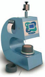
In laboratory setting time of cement is determined by standard Vicat apparatus. The initial setting time as well final setting time of cement is a indication of quality of cement. Now we will learn what the both setting times are.

a. Initial setting time:

This is the time when cement starts to stiffen remarkably

b. Final setting time:

This is the time when cement that get hardened to limit that it take some load.
Thus setting time of cement indicates the hydration of cement is in either normal or not satisfactory. In our regular construction process with cement it is desired that initial setting time should not be too small and final setting time should not be too large. Automatic Vicat Apparatus


To determine the both setting time both Gillmore needle and Vicat needle arrangement are used. The most common method is Vicat needle test. The specification of setting time of Portland Cement according to ASTM C150 are:


Test Method
Set Type
Time Specification
Vicat
Initial
≥ 45 minutes
Final
≤ 375 minutes
Gillmore
Initial
≥ 60 minutes
Final
≤ 600 minutes
Setting time of cement may be affected by:

1. Fineness of cement
2. Water-cement ratio
3. Chemical content(like gypsum)

Now what are the difference between concrete and cement?

There have wide difference between setting time of both. Though cement with some aggregate with presence of water produce a concrete mass, the setting time of cement is not the same that of concrete. In construction industry it is more important to know the setting time of concrete than that of cement. In concrete mix design sometimes some admixture or additives are used which may change widely the setting time of concrete. In ready mix concrete industry it is very common to use retarding admixture to delay the setting time until the concrete is reached to the placement site. The setting time of concrete is dependent on: 

a. Water/cement ratio

b. Temperature condition

c. Type of cement 

d. Admixture

Even curing methods According to ASTM C 403 the setting time of concrete is determined by pentrometer test.

How can Concrete be Made Pumpable?

Are you astonished? Why should concrete be pumped?

Now-a-days ready mix concrete is an essential part of concreting process. This plant or truck mixed concrete is transported to the site to place followed by other operations of concreting. In the project where concrete have to lift long vertical distance, it is the simplest way to pump it. The application suitable 
pump can lift concrete several hundred feet. To pump concrete mass it is required to make concrete pumpable.

Pumpable concrete has the properties not to be segregated or
bleeded with the right selection of constituent materials to bind all material, that consist concrete, under pressure. The requirements of mix are:

1. Under pumping pressure do not get segregated or bleeded.

600 m pumping of concrete at Burj Dubai.JPG
2. When concrete mix flows through the bends, it should have ability to deform.

3. The concrete mix must assist redial movement of adequate grout to provide and maintain initially provided lubricating film on the pipe line.


To reach these properties special cares are taken. These steps are:

a. The size of fines in the proportions should be less than 0.25 mm (approximately less than 300 microns). The fines are cement and other fine particles like sand. 


b. In the mix proportions 350-400 kg/cum fine particles are essential.
In Burj Dubai 600m single stage pumping of concrete to level 126
c. Concrete of slump 75 mm towards collapse range provides pumpability properties in concrete.


d. The pipe line should have diameter of >(3-4)times of the maximum aggregate size.  

What are Steel Formworks? How are They Used for Large Concrete Works?

Concreting works need form works to place concrete in required shape without leaking valuable water and cement to have excellent finishing surface as well as desire strength properties. Steel form works are strong, durable and can be used for several times with advantage of installation and dismantling with in small time. We will not discuss advantages of steel form works. In this post we will try to have overall idea of steel form works. 

These form works are fabricated in panels having thin steel plates which is stiffened by steel angles along all edges or as designed or strength requirement.
Steel form work made of plate with stiffener angle with bolting facilitySometimes diagonal flat bar are used to provide additional strength and stiffness. There have some arrangement like clamps, bolts to have make panels to work together. Horizontal or vertical centering of steel or timber facilitates the shuttering to keep in alignment and make the form work serviceable. The panels may of different shape and size. Usually a slab or wall panels are of (60 cmX60cm)-(60cmX120cm).

In case of curved shaped or circular structures like chimneys, columns, tanks etc, steel form work are essential to give the required shapes.

Steel form works are used in large construction works where several reuses of form works are required. In precast concreting process, these forms are used advantageously for repetitive casting operation.


Though they are relatively costly form works i.e. they require higher initial cost, they can be used more than a order of 100 times and economy is achieved for medium to large construction projects.

How can Concrete be Made more Impermeable?

A concrete mass consists of well graded aggregate having compacted well and of which segregation, bleeding and any sources of air voids are avoided successfully, is impermeable. This is more or less known to all engineers. In this post we will discuss about some compounds that render impermeable property to concrete.

These compounds are found as both liquid and powder form. Compounds like talc, chalk, fuller’s earth are used successfully in concrete industry to fill/eliminate the unexpected voids in concrete which makes concrete permeable.Thus concrete becomes water proof.

Concrete water proofing: 330 grams of Permo are used to each bag (50 kg) of cementSome compounds applied in concrete like aluminum sulfate, calcium chlorides, alkaline silicates etc, chemically reacts with concrete and produce a water proof mass of concrete.

Many prepared water proofing compounds are now available in the market. The most common compounds are Impermo, Pudlo, Permo, Sika etc. The application guidelines of water proofing compounds are printed in the package. The manufacturers provide amount of water proofing compounds per bag of cement and application method of them. The amount of water proofing compounds may be vary depending on the exposure condition of concrete. Normally 1 Kg of water proofing agent is added to 1 bag cement to produce a water proof concrete or mortar.

How can Hand Mixing of Concrete be Performed?

It is very interesting to know that a set of bad ingredient cannot produce a good concrete but a set of good ingredient cannot ensure a good concrete if intensive care is not taken. So to produce a good concrete it is required to know the good practice of concreting following the standard rules. Each stage of concreting process is important. Of the various stages of concreting, mixing, particularly hand mixing is discussed here.

To manufacture a concrete of uniform strength and durability properties, it should have uniformity. This uniformity is ensured by proper mixing of concrete. Mixing ensure a concrete mass of uniform color, consistency that produce a homogeneous mass of concrete. Mixing can be performed by two methods:

1. Hand mixing


2. Machine mixing

Dry mixing of cement and all aggregate before sprinkling of water in hand mixing of concreteImpervious brick or concrete floor is required as platform to mix all ingredients of concrete. The platform should be large enough to mix a concrete mix of one bag cement. At first according to the mix ratio the quantity of the coarse aggregate and fine aggregate are calculated. These two types of aggregate are spread in alternate layers. The cement are poured on top of them and in dry condition they are mixed by shovel. The mixture is turned over repeatedly to achieve a mixture of uniform color. When color becomes uniform, the mixer is spread in a thickness of around 200 cm. Now a water can having arrangement of sprinkling like rose-head are used to sprinkling the water. It should be noticed that water should be sprinkled not poured to avoid washout of green cement water. With sprinkling of water the turning over process is continued till a homogeneous and uniform concrete is found. It should be noticed that amount of water is determined from water/cement ratio as defined in mix design. Of this amount of water small amount of water is left not used. The rest water is added at the ending of mixing to just reach the required workability.
The most important things that I have forgotten to discuss is the feasibility of hand mixing. Hand mixing is exercised in small and less important concreting work. This is due to the probability of having inefficient and not uniform mix. A 10% excess cement is used sometimes to avoid inferior concrete that are supposed to produce by this method.

Why should Concrete be Remixed after Discharging from Mixer?

Concrete mixing machines are used for both reinforced concrete and mass concrete with some advantages like efficiency and sometimes economical in case of large volume concreting work. There have various mixers with variable efficiency in the concrete industry. In normal concreting work batch mixer is the right choice for concrete technicians. The batch mixer are of different types like pan type and drum type mixer.

Whatever the mixer, the discharging techniques of mixed concrete are important to avoid segregation. We know concrete is a mixer of cementing material and inert materials like coarse and fine aggregates which is to be bonded by the cementing materials like cement or lime in the presence of water with or without application of concrete admixture to render special properties or to ease placement and transportation work of concrete. Of which coarse aggregates, the heavier components of concrete, are supposed to segregate from the relatively lighter mix of cement and sand. When concrete is discharged from mixer, the heavy coarse aggregate falls first and then the matrix of cement and sand comes out resulting a little segregation. In some non-tilting drum concrete mixer have lever operated chute to facilitate the discharge without segregation.
Segregation of coarse aggregate and cement sand matrix after discharge from mixer
But whatever precautions are taken, it is noticed that segregation cannot be avoided. So to have workable and efficient concrete mix, a little remixing is required after discharge of concrete from mixer on the platform upon which mixed concrete are accumulated prior transporting to the placement site.
 Concrete drum mixer with discharge chute

How can Bleeding of Concrete be Reduced?

Bleeding is nothing but a segregation of concrete where some quantity of water is reached to surface creating some channels towards surface. Sometimes some amount of cement also comes out to the surface with the water. This phenomenon is observed in badly proportioned and inadequately mixed concrete or a mix having wetness of higher degree. Normally thin structural member like slabs show extensive bleeding. The bleeding channels described above produce a permeable concrete structure.
Bleeding dust of concrete results a nasty floor
Bleeding results laitance to concrete surface which results mud in wet conditionMore or less every engineer is known about bleeding. In this post we discuss how to reduce bleeding. The ways we can reduce bleeding are:

a. Proper proportioning of concrete mix can reduce bleeding.

b. A complete and uniform mixing of concrete also can reduce bleeding.
c. We have already known about the bleeding channel. If we can increase the traveling length of water to be bleeded, the bleeding can be reduced considerably. For this purpose we can use finely divided pozzolanic materials.

d. An introduction of air-entrainment by using air entraining agent can reduce bleeding phenomenon. 

Accumulated water from bleeding to concrete surfacee. The use of finer cement can reduce bleeding.

f. Application of cement of alkali-content can also reduced.

g. By using of a rich mix rather than lean mix can reduce bleeding.
Controlled vibration can reduce bleeding. When bleeding is appeared in the fresh and plastic concrete, revibration of concrete in controlled way can overcome detrimental impact of bleeding. 

How can Maintenance of Concrete Mixing Machine be Done?

Mixing of concrete is very important as a through and proper mixing produce a uniform concrete of homogeneous mass. It is desired to produce a mix of uniform consistency and color to have good workable concrete to facilitate placing and compaction work followed by mixing process. Now-a-days almost all concrete are mixed with concrete mixing machine for either reinforced concrete or mass concrete of large volume. Machine mixing is the most efficient method of mixing and in regard to economy it also provides economy to concrete production when a large scale concrete production is required. The time consumption for mixing concrete is also a fact to be considered.
Drum of concrte mixture in tilted position not carch rainwater and supported on firm support
Many types of mixer are available in concrete industry and their suitability is different depending on purpose to be served. Whatever the type it is very important to keep mixing running throughout the concreting work up to desired construction joint concreting are achieved. Thus nonstop concreting operation is very important in concrete industry. This purpose can only be achieved if concrete mixture is well maintained.
Blades catch concrete should clean after concreting operation
The mixer should be placed at the construction site on a leveled and firm platform. The blades with drum must always be cleaned after concreting operation. The skip must have proper support like sand bag cushion and should operate carefully. In case of not use, it should be noticed that the drum does not catch rain water or other source of water. In this regard; the drum can be kept covered or can be kept tilted position. 

Black Cotton Soils and Their Swelling Pressure

In India black cotton soils are found in the regions of Western Madhya Pradesh, Deccan plateau, Andhra Pradesh, some portion of Gujarat, Uttar Pradesh, Maharashtra and Karnataka covering more than 20% landmass of her. Here the soils that swell are named, as defined above, black cotton soil. Generally montmorillonite, the giant mineral portion of black cotton soils, becomes weathered to form less active particles of clay group like kaolinite and illite. But this process needs heavy weathering from rainfall. This active montmorillonite, when becomes saturated with water from a unsaturated state, it gets swelled and if reverse condition are occurred it gets shrunk. 

Geotechnical engineers are concerned with the magnitude of swelling pressure under desire environmental changes.


Swelling pressure:

Swelling pressure of soil is the maximum stress (Force/Area) that is required to keep the volume, supposed to be subject to swell, unchanged. This is a index that indicates how much trouble will exert an expansive soil. Usually a swelling pressure <20 kpa is not considered to be result much problem to foundation.ffff

Oedometer for One Dimensional Swell or Settlement Potential of Black cotton soil
The potential of a soil to swell is a function of loading condition and the water content expected to under foundation. The swell pressure and swell potential of black cotton soil can be examined by the ASTM (ASTM D 4546-90)Standard test procedure. This is the test method of cohesive soils for one dimensional or swells potential. If the soil sample are disturbed during sampling, the soil are compacted to achieved field water content and density as well with standard compaction mould like proctor. 

How can Water Table of Foundation Soil be Lowered?

There have many difficulties in foundation construction where water table is above the bottom level of foundation. To provide stability of foundation materials and to avoid difficulties in foundation construction, the only way is to lowering water table. The purpose is achieved by draining water to safe distance into galleries or ditches or pumping out from wells or sumps. This process is called gravity drainage as the gravity generates the force to flow the water to the designed drain.


This flow of water exerts a seepage pressure which forces the grains too with the water to the outlet. If there have silt or fine grained sand, finer constituents, they are washed out from the mix grained soil materials. They may clog drains, can result erosion tunnels or settlement to the drained soil. So this migration should be prevented. This purpose can be accomplished by using a filter that covers the drained materials with coarse materials of granular texture. The filter does not prevent the flow of water but the fine particle gets blocked by the small void of filter. 
providing granular filter for draining water from foundation soil
For satisfactory result from the filter, particle-size distribution curve of it should be suitably related to the soil materials to be filtered.

To mathematically depict the relation, filter ration R are used as follows:
filter ratio of filter for foundation soil
In addition to 50% and 15% sizes related requirements described by above expressions, the particle size distribution curve of filter material must have a smooth shape without sharp breaks and have to be parallel to the soil that have to be protected.
SI. NO.
Grading of filter material
R50
R50
1
Uniform where Cu ≤ 4
5-10
-----
2
Subrounded particles i.e. Nonuniform
12 -58
12-40
3
Angular Particles i.e. Nonuniform too
9-30
6-18
The particle size distribution curve of filter material must have a smooth shape without sharp breaks and have to be parallel to the soil that have to be protected.  

Foundation Settlement Due to Vibration

Generally vibration occurs in foundation when pile driving and blasting operation are done. This may be a part of construction operation of surrounding under construction buildings or for the new structure, that’s soil settlement are considered in design. The both operations are performed as a concept of compacting loose sand and subsidence is expected for new building but not expected for existing neighbor building if any.

As an example in a loose deposit of cohesionless soil 100 piles of 50 ft length were driven for same purpose of compaction. The result were occupied ground area settled 6 in. It was noticed that the settlement gradually decrease apart from pile driving area as an example at 50 ft apart the settlement was recorded only 1/8 in. So foundation engineers should be conscious about pile driving in such loose sand to avoid damage to surrounding structure. Sometimes other construction options are to be chosen leaving such vibration type foundation treatment.
Epoxy Grouts to reduce vibration from machine provided on foundation
Another source of vibration is arrived from machine foundation. It is very important to design machine foundation to have a period that has safe difference from the period of

Thickened foundation for machine foundation to absorb vibration.JPGadjacent soil to avoid possible resonance. Normally foundation weight is increased to absorb vibrations and distinguish period of both soil and foundation. There have a thumb rule of providing 2.5 times weight to foundation than that of machine to be supported.

Now, which type of soils suffers more due to vibration?
he cohesive soil suffers less impact from vibration. But alarming increment of relative density of cohessoinless soils are observed in this regard. This condition becomes worse to sands under water table or sand that is relatively dry. But sands above water table sometimes show sufficient cohesion not to re-arrange grain structure.

Erection Safety of Pile Rig

We all are concern with piling operation, investigating damaged pile, pile cap design and casting and other operation followed by them. But we are little concern with safety against piling hazard. In this post, we discuss erection of pile rig.

The frames of pile rigs must be checked safe structurally for expected dead, operational load and wind loads. If engineer in charge doubts structural strength, relevant test should be conducted to ensure any failure during operation or idle time. Every pile driving and operational equipments should be inspected and certified as safe. Guy line from all direction of flying hammer
In case of large project where two or more rigs are working at a time, a separation of distance more than longest leg of two rigs should be kept. 
Pile rig erection safety
Concrete beds, firm timber sills or any other secure foundations should be used as support of pile drivers. Sometimes pile drivers are guyed to withstand storm, wind, earthquake or other lateral impact. Normally three guys are required to have a least resistance to such impact. This safety measures are equally applicable to the rigs that are not even in use. Pile driver uplift

How can bearing capacity of shallow foundation be determined from permissible settlement?

This post concerned with plate bearing test. At first we have to know what plate bearing test. By this field test ultimate bearing capacity of soil and its settlement under designed load can be determined. In this test a steel plate is loaded at foundation level and settlement respective to load increment are recorded. The loads are gradually increased until the steel plate sinks at rapid rate. The ultimate bearing capacity of soil at foundation level is determined by the load at which plate sinks rapidly divided by area of steel plate. As we know, safe bearing capacity is a fraction of ultimate bearing capacity. This fraction is call factor of safety.
load-settlement curve from plate bearing test
A plot, known as load-settlement curve, on logarithmic scales (log-log plot) are done with load intensity as ordinates and settlement values as recorded in test as abscissa. In the plot two straight lines are found. The yield value or yield point is determined from intersection of two lines. This yield point is important in this discussion.

Now question is how to use this value. We realized, so far, in this discussion that safe bearing capacity is closely related to settlement of footing. The above load settlement curve provides ultimate bearing capacity and hence safe bearing.

The load intensity corresponding to yield point is the ultimate bearing capacity. From which using factor of safety 2-3 the safe bearing capacity is determined. This is safe bearing capacity for settlement.

The actual safe bearing capacity should smaller of following two:

a. Safe bearing capacity from settlement as derived from load-settlement curve.

b. Safe bearing capacity on the basis of shear failure

Piles in Tension in Pile Group

Generally the number of pile is determined by the axial load divided by capacity of each pile considering both end bearing and skin friction. But actual situation is there have always some reactions from lateral forces like earthquake and wind forces to piles as axial force, moment and shear force. The axial force is treated as usual. But the moment makes the differences in design and anchorage properties of both in pile and caps. In case of moment in pile cap, total reaction on each pile can be found by the expression below:
tension pile equation
Where, P=sum of reactions that are resulted from axial and moment

∑V= total vertical loads on foundation

n= number of piles in pile group
special anchorage for tension pile to pile cap
∑M=this is the sum of moments that have discussed above. The moment is not about center of gravity of cap but about center of gravity of pile group.

d= distance from the respective piles to the center of gravity of pile group.

If the p is positive there is no question of uplift and necessary anchorage. But if p is negative and piles in group are not anchored to pile caps the only a part of piles in pile group are in compression up to neutral axis. As the rest piles are not anchored to pile cap, these piles become ineffective as neither compression nor tension reactions are developed in them. The worse situation is, as some portion of piles in group is ineffective the compression reaction on the active piles is increased.

Thus it can be concluded that if piles in group are capable to withstand tension and sufficient anchorage to cap ia available the loads of each pile is calculated by the expression above.