Foundation, Concrete and Earthquake Engineering

What is Predrilling in Providing Pile Foundation in Plastic Clay?

The piles are the deep component of pile foundation system where some piles are embedded by thick embedment called pile cap. Any matter takes an amount of space just equal to its volume. The pile driven in the soil also takes its space and displacing, more accurately, a bit compacting surrounding soils. The plastic clay in saturated condition results a problem of displacing surrounding soil enough to disturb and sometimes result distress with a heaving phenomenon.


This heaving sometimes pull out a bit surrounding piles driven previously, resulting losing its capacity to transfer load to the firm stratum to which it was designed for. Sometimes this pile is required to be redriven.

Piles heaved out by driving of surrounding pile foundation

Now redriven produce a solution for piles, but how the distress of surrounding structures can be recovered. For this situation a method of drilling is used which is called predrilling. Piling in this type of soil results another problem as follows.


Sometimes lateral movements also associated with driving action. This problem is severe in unstable slope near the pile driving site. The severity reach extreme condition, when an existing excavation work or excavated site extends below pile driving level.

Predrilling is done to avoid distress of surrounding structures in driving pile foundation into plastic clay

Another problem arises where a composite pile is used as foundation pile. The heaving action sometimes releases the connection of joint bet two separate piling materials that comprises a complete pile.


So far we have discussed about problems of driving pile in such type of soil. Now we will learn how we can get rid of these situations. Where objections are coming from surrounding sites, slope failure is concerned, redriven produced extra cost and inconvenience to contractor, a method of removing part of soil from the space which is to be occupied by the pile. These method perform fairly good to avoid above situations.

In this purpose usually a predrilling is done with auger, sometimes rotary cutting equipment with the action of water jets. This method of cutting with jet transforms the problem soil, clay into heavy slurry.

Why are Piles Sometimes Required to be Redriven in Pile Foundation Construction?

We have published many posts about pile foundation. Of those posts, under-reamed pile foundation related posts have received thousands of visitors per month. We have published different aspects of pile testing, driving, boring and damaging to the same. In this post we will learn the fact when a driven pile is required to be redriven.


We have some posts and will publish many posts regarding drilling of piles in different type of soils. Now we will focus on plastic clay. It is very easy to think that a driven pile displaces soil and takes its own volume in the soil. But in case of bored pile the soils are removed or wash out to be occupied by a pile.

Heaved piles surrounding recently driven pile

The problem arises in driving through a plastic clay deposit that is in saturated condition. The plastic clay soil displaced by a driven piles results some kind of heaving action. This phenomenon is usually found in previously described saturated plastic clay. The heaving action may displace ground, lifting existing structures surrounding it. If a pile is previously driven near a heave forming pile it comes lift out.


As this pile is heaved out the bearing capacity of pile is required. That is end bearing of pile reduced and if this plastic clay remains in significant depth along the pile length, the skin resistance of pile assumed during capacity calculation also reduced.

How is Slab-On-Grade Foundation Repaired Distressed by Black Cotton Soil?

Black cotton soil is a expansive clay type soil. The behavior of this soil has discussed in previous many posts with its molecular structure. This soil is well known in India as every year many structures settled or suffered distress of any type due to expansive potential of this soil.


In United States this scenario is almost same. We have published many post regarding foundation problem and its repair options in United States. We are providing a figure regarding distribution of vertisol (expansive soil) in North America.

Distribution of Black Cotton ( Vertisols )Soil in North America

This is important fact that the destruction of buildings, pipelines and roads due to this expansive soil is more than twice that from combined destruction by tornadoes, hurricanes, floods and earthquakes.


Now we are going to describe repair method for such types of destruction to a particular foundation type. Here we will discuss about slab-on-grade foundation.

Black cotton soil of Deccan plateau

At first we will have a brief idea about slab on grade foundation. Slab on grade is a foundation that is poured on grade to serve as foundation for a structure. It is sometimes used as building floor. This slab may be reinforced or unreinforced. It depends on thickness and service load of the structure. It may rest on piles or piers, grade beams or any sort of supports.


Our concern is unreinforced or insufficient reinforced slab. Slab that support on other type of deep support is not considered here. This is due to they are less susceptible to be impacted by detrimental effect of black cotton soil. 
Now we will go to the main topics-the way of repair. The slab that have distressed either by shrinkage or heaving effect of black cotton soil is recommended to repair with structural slab. Now we will learn about how we can do this.


We are not mentioning that structural slab is the only option. But it is the most common solution for black cotton soil related distortion to slab-on-grade foundation. In one word, the existing distorted slab is removed and replaced with structural slab.

Settled pavement slab due to black cotton soil

Now what is structural slab? This is nothing but a slab having extra thickness and adequately reinforced for rendering moment resistance for expansive soil related movement.

We have mentioned that structural slab can be provided in replacement of unreinforced, not supported on firm foundation component or less thickened slab-on-grade foundations, as a foundation repair option for problem soil, black cotton soil.


How a structural slab is designed, depends on foundation engineer. In many cases, we have found that engineers are providing a thickness of five/six inches having steel reinforcement.


Construction of new structural slab having grade beam
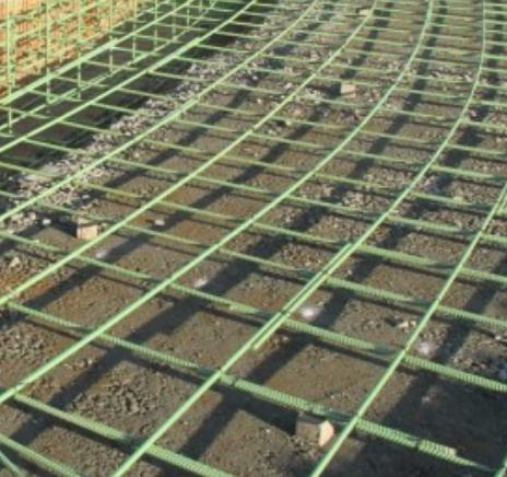
Regarding reinforcement 12 mm reinforcing bars (no.4 bars) are provided with a spacing of 450mm to 600mm center to center, and off course in both directions. We have mentioned earlier that this a typical or more accurately usual structural slab detailing and provided thickness. 


Depending on load of structure, purpose of use of slab, geotechnical condition (off course expansive property of black cotton soil is considered), designer may vary the detailing and thickness.


Slab-on-grade foundation may rest on shallow or deep component of foundation systems. There may be a load bearing footing below a slab and sometimes it is expected to remain this component. For these purpose a concrete saw is used to cut the slab. Our aim is to leave the narrow weak slab just over the support provided by load bearing wall. It (the support) may be some sort of grade beam. 


As mentioned earlier, the narrow and weak slab should be cut along the side of support say load bearing wall or grade beam or other means of support. Now we have isolated this narrow slab on the support from the unsupported narrow one. This is the time to provide new structural slab as repair option of distressed slab-on-grade foundation.


Every new work should have a proper connection with older one. Now we will learn how we will do this. We will provide a means of connection named “rebar dowel” to the remaining older one. Now do we know what is rebar dowel. 

Rebar doweling required for a insufficient reinforced distressed slab foundation cut over footing support
In the process of rebar doweling, horizontal holes are drilled through vertical face of old remaining concrete and pieces of rears, glued with epoxy are penetrated. In drilling purpose hammer drill or roto-hammer is used. In the next post we will have idea about drilling size and depth requirements and also economical fact of this method of slab-on-grade foundation repair.
Splicing new bars with rebar dowels, previously drilled and glued with epoxy for repairing slab-on-grade foundation

The manufacturer of epoxy will provide hole size and penetration depth for rebar of particular size. We will provide some epoxy products from different manufacturers for applying rebar dowels in next post.


Now we will consider the economy of this repair process. In some cases, the severity of problem due to expansive soil, governs the way of repair method. If the depth of black cotton soil is relatively small, it is wise to remove it and backfilled with non-expansive soil. 


Rebar doweling for slab extension to form slab foundation

We have published a post about fill material as a replacement of this problem soil. Foundation engineers have to consider this economical fact. But when the large depth of replacement produces huge cost involvement, structural slab is better option.

Mud jacking is also a method of repair for such problems. But mud jacking may involve grout losses for many reasons. Regarding grout losses during mud jacking as discussed earlier, some methods of containment of grout have to use. These containments involve further cost involvement. So the economy depends on geological and geotechnical conditions of the foundation sites.

How is Polymer Concrete System Formed?

This type of concrete is generally used for grout pads, overlays, patches and silt embedment purposes, and for similar purposes in concrete. This is a technique of repair concrete members. we will discuss about this system of concrete in this post. Gradually we will discuss all types of concrete repair method in this blog.


Normally vinyl ester resin and methyl methacrylate are used as polymer system. now we will learn about what consists this system of concrete. These are:


A. Resin system or reactive monomer (100%). generally there should only reactive solvent.

Polymer Concrete overlay for bridge deck
B. To avoid premature polymerization of the system of monomer or resin, inhibitors are used. These inhibitors are normally used in monomer by acrylic manufacturers requiring no mixing in site.

C. To retard decomposition rate of initiator, a small quantity of promoter is used.

D. The quantity of initiator has a relation of direct proportion with the curing rate of polymer concrete.

E. Necessarily aggregates

F. As an extra acre a primer that is compatible with this type of concrete is applied over the surface of concrete that have to be repaired.


The application of polymer concrete system renders a set of physical properties of upgraded form to the repaired concrete. They are:

1. Compressive strength

2. Tensile strength

3. Flexural strength

4. Modulus of elasticity

Economic Considerations in Selecting Foundation in Black Cotton Soil

Generally two types of foundation are adopted in broad sense. They are:

a. Deep supporting system

b. Shallow supporting system


Before go through the main topic we will briefly discuss about both system of foundation.


Deep supporting system:

The foundation that has deep component extending well below the active zone of moisture in soil is called a foundation having deep supporting system. The active zone is important as the only enemy to foundation on black cotton soil is moisture. Thus moisture fluctuation does not disturb the foundation system. Plies or drill piers are the ideal example of this type of system.


Under reaming operation for under reamed piles for black cotton soilShallow supporting system:

The foundation system that does not extend beneath the active zone of moisture is termed as shallow supporting system. As the foundation component remains in moisture zone, the foundation and the structure as well suffer movements as supporting expansive soils get expanded due to activity of moisture.


Now we are ready to discuss the economic considerations. The foundation systems discussed above both have risk of damage due to differential settlement. We have to know about the cost involvement and reduction or increment of risk for particular foundation system. 

Both deep supporting and shallow supporting systems have risk of differential settlement. Differential settlement causes disturbance to superstructure and destruction of architectural elements of the structure. Both methods involve with respective cost involvement. Obviously the deep supporting system of construction involves relatively more cost.

Failure of foundation wall due to "clay bowl effect" of backfill black cotton soil

The fact related to risk and cost is that degree of risk has a proportion of inverse order to cost. But when heavy cost involvement is concerned, sometimes higher risk of foundation failure is accepted. So shallow foundation system is sometimes adopted knowing greater risk involvement considering economy and affordability.


Now question is how we can select foundation system satisfying both risk and economy. The answer is-it is impossible to meet both conditions. So owners or developers have to take a tough discussion. Normally two lists are made to determine a better solution. These are:


a. Listing foundation system in increasing level of risk.

b. Listing foundation systems in decreasing construction cost.

From these two lists one can choose the better options of foundation system for his/her sweet home or commercial or industrial structure to be rested on black cotton soil.

Surface Preparation for Commencing Concrete Repair Work

To make a composite concrete member having composite action, this bonding is very important and to achieve this it is very important to prepare the surface of concrete to be bonded with foreign repair materials. It is also important to provide bonding with reinforcement present in old concrete member. In this post we will learn about surface preparation techniques. We will discuss these in four consecutive posts.


In the figure below we described a typical removal area of spalled concrete to be repaired. In this figure we provide delaminated or loosen concrete boundary in the left side and recommended preparation layout for commencing repair work.


Fig-1: A typical layout for surface repair as an example
Typical Surface Preparation layout for concrete repair

For the convenience of the reader we will provide some sketch for example and images of some pectical work performed before repair work and finished concrete surface after repair work. For these repair positioning and placement of formwork is very important.

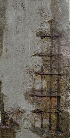
To provide perfect bond between old and new concrete the engineers and supervisors should carefully inspect the reinforcement that are exposed due to either corrosion or come out during removing loose and delaminated concrete. These include:

Exposing reinforcing bar before repair work of a concrete column
a. Access clearance

b. Cross-sectional area of reinforcement, if the section is corroded.

c. Location of reinforcement


When reinforcing steel is not properly bonded with the prepared concrete (dismantled delaminated and spalled concrete free surface) then the reinforcing bar has to be exposed to a further depth. Normally the further exposing is done when the prepared surface does not reach to half of the perimeter of reinforcing bar. When it reached to more than half of the perimeter of reinforcing bars, the bar is exposed completely. 

Normally a disc type mechanical cutter is used to expose bar without reducing or cutting the remaining reinforcing bars. Now we will discuss the remaining task to be done for removing loose concrete around reinforcing bars. 
Concrete repair: Corroded reinforcement, sectional reduction more than 15%

When fully exposing is concerned, a question arises how much gap between reinforcement and prepared concrete should be kept. The clearance is


Average clearance=25 m

Average clearance= (Maximum aggregate size+5) mm

Greater of the two are provided as a clearance between reinforcement and concrete surrounding it.


So far we learned about removing loose concrete and making clearance between them. Now we have to observe the condition of reinforcing bars. The things to be noticed that

a. For individual bar, cross-sectional area must not reduced ≥15%

b. For adjacent two bars, cross-sectional area must not reduced ≥10%

c. Loose reinforcement and its location in out of plane should rearrange and relocated.

For the above cases a structural engineer should be appointed to justify the further progress can be carried out. Generally sand blasting the concrete surfaces is adopted to prepare a concrete surface and that of reinforcement to have optimum bonding. Then debris and dust are removed by following procedure:

Anti-corrosive coating to reinforcement before concrete repair work
a. Booming or

b. Air blasting or

c. Water blasting with low pressure


In case of exposed concrete surface, a coating that suit best is applied. This should keep in mind that the rust from the surface of reinforcement must be removed thoroughly. The consideration of coating is taken where corrosion environment is found around the concrete member or existing reinforcement in concrete is found corroded. We have already discussed about allowance of degree of corrosion. With all types of measures undertaken carefully, finally engineer should inspect for any other deficiencies that may be overlooked before and take remedial action instantly to start next phase of repair work. 

Requirements for Wash Water for Using in Ready-Mixed Concrete

In permitting water to be used in mixing of concretethe quality should be potable and many other chemical and biological aspects also should consider . Now question is wash out water can be used in further concreting operation.


The wash water received from washout operations of mixer can be used if it complies with limit stated in table-1 provided below. This table provides limits for physical test of questionable water.


Table-1: the criteria for accepting wash water supply
Criteria for accepting wash water supply for Using in ready mixed concrete
Regarding application of air-entrainment and chemical admixtures of other forms ASTM C94/C94M-00 provides that special attention should pay to determine the rate of dosages and sequence of batching. These determined amount and sequences should apply to consecutive batches.


ASTM C94/C94M specifies the requirement for ready mixed concrete. We will publish numerous post regarding requirements and specifications for ready mixed concrete. For convenience of reader we will sometimes provide combination of ASTM and ACI specifications for particular topics regarding ready mixed concrete.
Regarding testing frequency ASTM specifies that throughout the first 4 weeks the test should be conducted in a interval of a week. After that a monthly interval of testing can be accepted frequency. In each test the results must not exceed the limit stated in table-1.


The purchaser can specify the testing frequencies for chemical limits or the frequencies specified before can be used for these tests.

The chemical limit test is specified as option in this standard. But purchaser can specify to test for these limits. 

Table-2: optional limits for chemical content in wash water
Optional limits for chemical content in wash water in ready mixed concrete

How are Soilcrete Column Constructed with Deep Soil Mixing?

We have discussed about soilcrete columns in previous posts. In this post we will learn about deep soil mixing technique for constructing soilcrete structural elements. This is a method of injecting cement slurry named grout to required depth to stabilize foundation soil to have better engineering properties of soil.


A mixing tool is used to blend soil with grout. The mixing tool is hollow to facilitate grout to inject through it. In this method of mixing, the tools used for mixing consists of cutters or blades and paddles. The all elements are designed and arranged to facilitate mixing and agitation of soil-cement slurry to construct columns of soilcrete of diameter ranging from (3-8) ft. the resulting columns rendered a compressive strength of the order of (200-600)psi.
Soilcrete column construction to provide additional support Earth retaining structure


If the existing soil is saturated, sometimes cement can be injected as powder. There a insitu hydration of cement is occurred. The dry powder injection in this method serves the purposes as that of cement slurry injection.


Either powder or slurry injection render a stabilized soil mass of increased bearing capacity, less settlement susceptibility. Thus the stabilization options mitigate earthquake liquefaction hazards that are very frequent in soft soils. This method is especially suitable for treating foundation soil that have to support a structure having large footprints like slab foundation or storage tank.

What are the Performance Requirements to Adopt an Effective Concrete Repair Method?

In the previous post we have discussed many aspects of concrete repair work. We have discussed about repair options that can be taken and also published few posts about RCC jacketing. In this post we will discuss about the performances that should expect from selecting a repair option (as discussed in previous post).


The performance requirements include the achievement of desired strength, durability and serviceability from a repair system. The protection of steel reinforcement that is suspected to be corroded is also important. The most important requirement that ensure composite action is bond between parent materials to new materials that are used to repair a existing member of structure. Here we are providing a list of such requirements to ensure good performance:

Concrete surface preparation by removing spalled and loose particles to provide repair work.

1. Proper protection to steel.

2. Bond between parent and new materials.

3. Dimensional stability.

Spalled and corroded concrete column required to be repaired4. Sufficient resistance against most unfavorable environmental damage.

5. Appearance of final product/member.

6. Affordable and easy application.

And as a whole the final requirement is a strong, serviceable and durable repaired product.

In achieving such performance the following factors should be considered during selecting a method of repair:

a. Extent and type of distress

b. Environmental distress

c. Distress location

d. Accessibility to repair location

e. Duration of repair work

f. Cost

g. Appearance

h. Available workmanship

How are Soilcrete Columns Constructed With Jet Grouting?

We discussed in previous post that soilcrete column can be constructed either by deep soil mixing or jet grouting. We have learned that deep soil mixing may be wet mix and dry soil mix. Now we will learn about jet grouting techniques to form soilcrete column to strengthen soft or weak foundation soil to have a better founding medium to transfer structural loads.


This technique is used for stabilization of tunnel, underpinning purposes especially in confined condition, bottom seals for excavation, supporting utility premises. To strengthen existing older structure to comply with recent earthquake codes or to solve settlement problem of existing buildings, low headroom drilling rig is generally used.
Shear Wall Construction with Soil-Crete technique with jet grouting

Now we will learn about grouting techniques. This is a process where cement slurry, named grout, is injected into ground to replace or erode the existing soft soil with the grout (as termed before). Holes of (4-8) inch diameter are drilled in to ground to designed depth. After reaching desired depth grouting is injected through a system of nozzles attached to drill rods near bottom of it. Regarding depth limit, it can be said that 120’ depth is typical but a greater depth can be used to injecting grouts.


Through these nozzles a pressure up to 500 psi is used to pump a mixer of grout with water or air. As the pumping is progressed, the drill rods are withdrawn rotating slowly from the hole. This procedure forms a typical (3-10) ft diameter soilcrete column. These rigid soilcrete columns show average compressive strength in confined condition ranging from (250-1250) psi.


As we discussed earlier and in previous post that soilcrete is a technique to strength soil against foundation settlement and increasing bearing capacity to mitigate earthquake generated liquefaction hazards. The application of drilled shaft and piling or by replacing existing weak soil, we can also mitigate such hazard. But soilcrete is a cheap way to serve these purposes. The foundation engineers should consider this option before selecting more expansive solution as described above.

What are Dry Soil Mix and Wet Soil Mix in Soilcrete?

In the previous post we have learned that structural elements of soilcrete can be constructed either by soil mixing or jet grouting. In this post we will learn about soil mixing. In this method of mixing, the tools used for mixing consists of cutters or blades and paddles. The all elements are designed and arranged to facilitate mixing and agitation of soil-cement slurry to construct columns of soilcrete of diameter ranging from (3-8) ft. the resulting columns rendered a compressive strength of the order of (200-600)psi.


So far we discussed about injection of mixer in the form of slurry. But in some cases a dry powdered form mixer may produce a soilcrete column. This is done in saturated soil. Here in situ hydration is occurred. The method of injecting mixer in dry powdered form and hydration process in situ is called dry soil mixing.

1.5m excavated Soilcrete Column to be interconnected with beams

The dry mix produces a soilcrete column as that can be produced by cement slurry having no significant waste. If we term later process as dry soil mix, the first method can be termed as wet soil mix.


Construction of soilcrete columns is a technique to improve stiffness and strength properties of soft/weak soils. A geotechnical engineer should consider soilcrete techniques before selecting more expensive options like drilled shafts, piling or other expensive options.

Where to Apply Soilcrete: A Stabilization Option

We have already got an idea about soilcrete. Now we will learn where this method should be used as Soil stabilization options. It is very uncommon to have a building site of having geotechnical and geological conditions in favor of structural and geotechnical design of building and most of times the engineers find a mitigation option to safely transfer structural loads to the ground. In case of ideal soil condition like dense sand or gravel, we need not to think about soilcrete. A simple foundation like column footing or hardly combined footing is safe for it with any application of stabilization.


The geotechnical engineers is afraid of the earthquake induced settlement due to liquefaction or from other causes of settlement in loose or soft soil deposits beneath the structure to be founded. The safest way is to transfer loads to stronger stratum for such type soil. 

1.5m excavated Soilcrete Column for stabilization of foundation soil

Like above method another safe method is to replacing soft and poor engineering quality soil with ideal soil sated above with designed percent compaction of this ideal soil. We discussed about percent compaction in previous post. Please follow this link above to have ideal about it.


In many situations the construction cost of piling/drilling shaft/replacing soft soil, is not feasible considering benefit-cost relationship and in some situations they are not also practical considering difficulties of construction. Soilcrete can effectively solve the problems of settlement hazards and bearing capacity failure, with a low cost involvement. This method also saves valuable construction duration in compare to conventional deep foundations or replacement options.

What is Soilcrete in Soil Stabilization?

Soilcrete is a method of rendering better engineering properties to foundation soil. Throughout this month we have discussed different way of stabilization of soil that suits for particular soil types. Here we will publish some consecutive posts about soilcrete. We have already learned about pozzocrete and shotcrete. This version of ‘crete’ is different from these.


In this method of soil stabilization, soil is mixed with Portland cement and water. The mixing is done in situ by excavating soil and mixing it with cement and water by blending with mechanical mixer and sometimes fluid is injected in high pressure.


Shear Wall Construction with Soil-Crete technique
Soilcrete is used in either grid pattern or in pinpoint where concentration of structural loads is high. The first option is used where entire substructure are needed to be treated to provide foundations like slab foundation or storage tank. The later option is applicable in heavily loaded critical components of building for which stabilization of foundation soil is required.


The foundation bed that have soft or loose deposits, suspected to be suffered excessive settlement hampering regular serviceability of building structures disturbing, the most common, utility facilities. In the next post we discuss about he applications of this methods. The most common methods of constructing structural elements of soilcrete are soil mixing and jet grouting. We will discuss about these two methods in next few posts. Please stay tuned with this blog.

How can French Drains be Used to Prevent Black Cotton Soil Related Problems?

We have discussed many aspects of foundation problems associated with black cotton soils in previous several posts. Our most successful post, about black cotton soil, “Foundation on black cotton soil” has become very popular and we are receiving thousands of viewers for this post. In this post we will discuss about French drains that can be used to drainage control within the foundation soils and thus restricting many harmful impact from black cotton soil.


At first we will learn about French drains in brief. French drains are trenches that are filled with gravel. This granular fill captures moisture that are intending to pass through fill. The fills of gravels the removes unwanted moisture through a pipe or system of pipes. Generally a set of perforated pipes are placed at the bottom portion of trench. These perforated pipes collects moisture that accumulated below the fills through the gravel fills and then discharge to a suitable point situated at the end of these pipes.


French drain for black cotton soil related foundation problem
Thus a well planned and distributed perforated pipe system in between French drain provides a barrier to groundwater flow towards foundation. This renders a inert properties to black cotton soil as black cotton soils shows its destruction capacity when it receives moisture from ambient environment.


The French drains are suitable where water table is high and subgrade soils are receiving a huge volume of water. A small modification to this makes it to perform as cut-off wall. The modification is providing a heavy and thick plastic liner between foundation of building structures and French drain.

How can Cut-off Wall be Used for Multiple Solutions for Foundation Problems Associated with Black Cotton Soil?

We have already discussed many posts about problems and necessary solutions for foundation problems associated with black cotton soils and expansive soils as well. Many of these posts are about drainage control. In this post we will discuss another method of drainage control in black cotton soils. 


Drainage control is the only cheapest way to rehabilitate an existing foundation. Depending on the various methods of drainage control the cost involvement are different. Here application of cut-off wall as drainage control will be discussed. The phrase ‘multiple solutions’ is used as it is also a means of underpinning for a foundation to be rehabilitated. 


Construction of Cut Off Wall
The cut-off wall is a barrier that prevents moisture to penetrate horizontally to a foundation system. These are a vertical walls to restrict movement of moisture from either side of it - both from foundation outer perimeter ground and outer to foundation sides. He who deals with expansive soil like black cotton soil, knows the importance of moisture barrier in controlling both swelling and shrinkage properties of soils. By preventing moisture gaining and releasing, a black cotton soil may behave as inert material.


Now we will learn about cut-off wall. Cut-off walls can be made of concrete which is attached or abuts to perimeter of existing foundation to be repaired. With the purpose of drainage control, they may provide a provision to transfer the loads that are arrived from structure through foundation to deeper stratum of soils. Thus they may be used as an option of underpinning which is required to perform a further rehabilitation purposes.

What are Soil Cement Piles in Soil Stabilization?

In the recent posts we have discussed about soil compaction methods and different soil stabilization methods to improve the properties of foundation soil for expansive soils, collapsible soils and usual soil types. In this post we will discuss about soil cement piles. We will discuss about design process and other aspects of this method of soil stabilization in consecutive posts.


This method is relatively new in development in soil improvement. We will define this method as SCP (soil cement piles) for convenience of explanation. In SCP an especial drill bit is used for grinding and cutting of soils. During penetration, cement slurry with the addition of suitable additives, is injected. A shear blade is fixed above drill head that holds soil between this blade and drill to facilitate the mixing of cement slurry with soil. For this purpose the blade diameter is kept a bit larger than hole diameter so that the blade it can fix into the wall of bored hole.

An Excavated Soil Cement Piles

The drill is taken out when desire depth is reached, leaving a piles of soil cement. During withdrawal process, counter-rotation is rendered to have further blending of cement slurry that are injected during penetration and soil cutting.


This method of soil improvement is extremely rapid. The SCP of ranging (0.6-1)m diameter can be produced rapidly having up to a depth ranging from(1.5-10)m. A maximum depth limit of 35m is practical.

Followers