Economic Considerations in Selecting Foundation in Black Cotton Soil

Generally two types of foundation are adopted in broad sense. They are:

a. Deep supporting system

b. Shallow supporting system


Before go through the main topic we will briefly discuss about both system of foundation.


Deep supporting system:

The foundation that has deep component extending well below the active zone of moisture in soil is called a foundation having deep supporting system. The active zone is important as the only enemy to foundation on black cotton soil is moisture. Thus moisture fluctuation does not disturb the foundation system. Plies or drill piers are the ideal example of this type of system.


Under reaming operation for under reamed piles for black cotton soilShallow supporting system:

The foundation system that does not extend beneath the active zone of moisture is termed as shallow supporting system. As the foundation component remains in moisture zone, the foundation and the structure as well suffer movements as supporting expansive soils get expanded due to activity of moisture.


Now we are ready to discuss the economic considerations. The foundation systems discussed above both have risk of damage due to differential settlement. We have to know about the cost involvement and reduction or increment of risk for particular foundation system. 

Both deep supporting and shallow supporting systems have risk of differential settlement. Differential settlement causes disturbance to superstructure and destruction of architectural elements of the structure. Both methods involve with respective cost involvement. Obviously the deep supporting system of construction involves relatively more cost.

Failure of foundation wall due to "clay bowl effect" of backfill black cotton soil

The fact related to risk and cost is that degree of risk has a proportion of inverse order to cost. But when heavy cost involvement is concerned, sometimes higher risk of foundation failure is accepted. So shallow foundation system is sometimes adopted knowing greater risk involvement considering economy and affordability.


Now question is how we can select foundation system satisfying both risk and economy. The answer is-it is impossible to meet both conditions. So owners or developers have to take a tough discussion. Normally two lists are made to determine a better solution. These are:


a. Listing foundation system in increasing level of risk.

b. Listing foundation systems in decreasing construction cost.

From these two lists one can choose the better options of foundation system for his/her sweet home or commercial or industrial structure to be rested on black cotton soil.

Surface Preparation for Commencing Concrete Repair Work

To make a composite concrete member having composite action, this bonding is very important and to achieve this it is very important to prepare the surface of concrete to be bonded with foreign repair materials. It is also important to provide bonding with reinforcement present in old concrete member. In this post we will learn about surface preparation techniques. We will discuss these in four consecutive posts.


In the figure below we described a typical removal area of spalled concrete to be repaired. In this figure we provide delaminated or loosen concrete boundary in the left side and recommended preparation layout for commencing repair work.


Fig-1: A typical layout for surface repair as an example
Typical Surface Preparation layout for concrete repair

For the convenience of the reader we will provide some sketch for example and images of some pectical work performed before repair work and finished concrete surface after repair work. For these repair positioning and placement of formwork is very important.

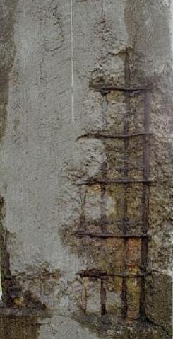
To provide perfect bond between old and new concrete the engineers and supervisors should carefully inspect the reinforcement that are exposed due to either corrosion or come out during removing loose and delaminated concrete. These include:

Exposing reinforcing bar before repair work of a concrete column
a. Access clearance

b. Cross-sectional area of reinforcement, if the section is corroded.

c. Location of reinforcement


When reinforcing steel is not properly bonded with the prepared concrete (dismantled delaminated and spalled concrete free surface) then the reinforcing bar has to be exposed to a further depth. Normally the further exposing is done when the prepared surface does not reach to half of the perimeter of reinforcing bar. When it reached to more than half of the perimeter of reinforcing bars, the bar is exposed completely. 

Normally a disc type mechanical cutter is used to expose bar without reducing or cutting the remaining reinforcing bars. Now we will discuss the remaining task to be done for removing loose concrete around reinforcing bars. 
Concrete repair: Corroded reinforcement, sectional reduction more than 15%

When fully exposing is concerned, a question arises how much gap between reinforcement and prepared concrete should be kept. The clearance is


Average clearance=25 m

Average clearance= (Maximum aggregate size+5) mm

Greater of the two are provided as a clearance between reinforcement and concrete surrounding it.


So far we learned about removing loose concrete and making clearance between them. Now we have to observe the condition of reinforcing bars. The things to be noticed that

a. For individual bar, cross-sectional area must not reduced ≥15%

b. For adjacent two bars, cross-sectional area must not reduced ≥10%

c. Loose reinforcement and its location in out of plane should rearrange and relocated.

For the above cases a structural engineer should be appointed to justify the further progress can be carried out. Generally sand blasting the concrete surfaces is adopted to prepare a concrete surface and that of reinforcement to have optimum bonding. Then debris and dust are removed by following procedure:

Anti-corrosive coating to reinforcement before concrete repair work
a. Booming or

b. Air blasting or

c. Water blasting with low pressure


In case of exposed concrete surface, a coating that suit best is applied. This should keep in mind that the rust from the surface of reinforcement must be removed thoroughly. The consideration of coating is taken where corrosion environment is found around the concrete member or existing reinforcement in concrete is found corroded. We have already discussed about allowance of degree of corrosion. With all types of measures undertaken carefully, finally engineer should inspect for any other deficiencies that may be overlooked before and take remedial action instantly to start next phase of repair work. 

Requirements for Wash Water for Using in Ready-Mixed Concrete

In permitting water to be used in mixing of concretethe quality should be potable and many other chemical and biological aspects also should consider . Now question is wash out water can be used in further concreting operation.


The wash water received from washout operations of mixer can be used if it complies with limit stated in table-1 provided below. This table provides limits for physical test of questionable water.


Table-1: the criteria for accepting wash water supply
Criteria for accepting wash water supply for Using in ready mixed concrete
Regarding application of air-entrainment and chemical admixtures of other forms ASTM C94/C94M-00 provides that special attention should pay to determine the rate of dosages and sequence of batching. These determined amount and sequences should apply to consecutive batches.


ASTM C94/C94M specifies the requirement for ready mixed concrete. We will publish numerous post regarding requirements and specifications for ready mixed concrete. For convenience of reader we will sometimes provide combination of ASTM and ACI specifications for particular topics regarding ready mixed concrete.
Regarding testing frequency ASTM specifies that throughout the first 4 weeks the test should be conducted in a interval of a week. After that a monthly interval of testing can be accepted frequency. In each test the results must not exceed the limit stated in table-1.


The purchaser can specify the testing frequencies for chemical limits or the frequencies specified before can be used for these tests.

The chemical limit test is specified as option in this standard. But purchaser can specify to test for these limits. 

Table-2: optional limits for chemical content in wash water
Optional limits for chemical content in wash water in ready mixed concrete

How are Soilcrete Column Constructed with Deep Soil Mixing?

We have discussed about soilcrete columns in previous posts. In this post we will learn about deep soil mixing technique for constructing soilcrete structural elements. This is a method of injecting cement slurry named grout to required depth to stabilize foundation soil to have better engineering properties of soil.


A mixing tool is used to blend soil with grout. The mixing tool is hollow to facilitate grout to inject through it. In this method of mixing, the tools used for mixing consists of cutters or blades and paddles. The all elements are designed and arranged to facilitate mixing and agitation of soil-cement slurry to construct columns of soilcrete of diameter ranging from (3-8) ft. the resulting columns rendered a compressive strength of the order of (200-600)psi.
Soilcrete column construction to provide additional support Earth retaining structure


If the existing soil is saturated, sometimes cement can be injected as powder. There a insitu hydration of cement is occurred. The dry powder injection in this method serves the purposes as that of cement slurry injection.


Either powder or slurry injection render a stabilized soil mass of increased bearing capacity, less settlement susceptibility. Thus the stabilization options mitigate earthquake liquefaction hazards that are very frequent in soft soils. This method is especially suitable for treating foundation soil that have to support a structure having large footprints like slab foundation or storage tank.

What are the Performance Requirements to Adopt an Effective Concrete Repair Method?

In the previous post we have discussed many aspects of concrete repair work. We have discussed about repair options that can be taken and also published few posts about RCC jacketing. In this post we will discuss about the performances that should expect from selecting a repair option (as discussed in previous post).


The performance requirements include the achievement of desired strength, durability and serviceability from a repair system. The protection of steel reinforcement that is suspected to be corroded is also important. The most important requirement that ensure composite action is bond between parent materials to new materials that are used to repair a existing member of structure. Here we are providing a list of such requirements to ensure good performance:

Concrete surface preparation by removing spalled and loose particles to provide repair work.

1. Proper protection to steel.

2. Bond between parent and new materials.

3. Dimensional stability.

Spalled and corroded concrete column required to be repaired4. Sufficient resistance against most unfavorable environmental damage.

5. Appearance of final product/member.

6. Affordable and easy application.

And as a whole the final requirement is a strong, serviceable and durable repaired product.

In achieving such performance the following factors should be considered during selecting a method of repair:

a. Extent and type of distress

b. Environmental distress

c. Distress location

d. Accessibility to repair location

e. Duration of repair work

f. Cost

g. Appearance

h. Available workmanship

How are Soilcrete Columns Constructed With Jet Grouting?

We discussed in previous post that soilcrete column can be constructed either by deep soil mixing or jet grouting. We have learned that deep soil mixing may be wet mix and dry soil mix. Now we will learn about jet grouting techniques to form soilcrete column to strengthen soft or weak foundation soil to have a better founding medium to transfer structural loads.


This technique is used for stabilization of tunnel, underpinning purposes especially in confined condition, bottom seals for excavation, supporting utility premises. To strengthen existing older structure to comply with recent earthquake codes or to solve settlement problem of existing buildings, low headroom drilling rig is generally used.
Shear Wall Construction with Soil-Crete technique with jet grouting

Now we will learn about grouting techniques. This is a process where cement slurry, named grout, is injected into ground to replace or erode the existing soft soil with the grout (as termed before). Holes of (4-8) inch diameter are drilled in to ground to designed depth. After reaching desired depth grouting is injected through a system of nozzles attached to drill rods near bottom of it. Regarding depth limit, it can be said that 120’ depth is typical but a greater depth can be used to injecting grouts.


Through these nozzles a pressure up to 500 psi is used to pump a mixer of grout with water or air. As the pumping is progressed, the drill rods are withdrawn rotating slowly from the hole. This procedure forms a typical (3-10) ft diameter soilcrete column. These rigid soilcrete columns show average compressive strength in confined condition ranging from (250-1250) psi.


As we discussed earlier and in previous post that soilcrete is a technique to strength soil against foundation settlement and increasing bearing capacity to mitigate earthquake generated liquefaction hazards. The application of drilled shaft and piling or by replacing existing weak soil, we can also mitigate such hazard. But soilcrete is a cheap way to serve these purposes. The foundation engineers should consider this option before selecting more expansive solution as described above.

What are Dry Soil Mix and Wet Soil Mix in Soilcrete?

In the previous post we have learned that structural elements of soilcrete can be constructed either by soil mixing or jet grouting. In this post we will learn about soil mixing. In this method of mixing, the tools used for mixing consists of cutters or blades and paddles. The all elements are designed and arranged to facilitate mixing and agitation of soil-cement slurry to construct columns of soilcrete of diameter ranging from (3-8) ft. the resulting columns rendered a compressive strength of the order of (200-600)psi.


So far we discussed about injection of mixer in the form of slurry. But in some cases a dry powdered form mixer may produce a soilcrete column. This is done in saturated soil. Here in situ hydration is occurred. The method of injecting mixer in dry powdered form and hydration process in situ is called dry soil mixing.

1.5m excavated Soilcrete Column to be interconnected with beams

The dry mix produces a soilcrete column as that can be produced by cement slurry having no significant waste. If we term later process as dry soil mix, the first method can be termed as wet soil mix.


Construction of soilcrete columns is a technique to improve stiffness and strength properties of soft/weak soils. A geotechnical engineer should consider soilcrete techniques before selecting more expensive options like drilled shafts, piling or other expensive options.

Where to Apply Soilcrete: A Stabilization Option

We have already got an idea about soilcrete. Now we will learn where this method should be used as Soil stabilization options. It is very uncommon to have a building site of having geotechnical and geological conditions in favor of structural and geotechnical design of building and most of times the engineers find a mitigation option to safely transfer structural loads to the ground. In case of ideal soil condition like dense sand or gravel, we need not to think about soilcrete. A simple foundation like column footing or hardly combined footing is safe for it with any application of stabilization.


The geotechnical engineers is afraid of the earthquake induced settlement due to liquefaction or from other causes of settlement in loose or soft soil deposits beneath the structure to be founded. The safest way is to transfer loads to stronger stratum for such type soil. 

1.5m excavated Soilcrete Column for stabilization of foundation soil

Like above method another safe method is to replacing soft and poor engineering quality soil with ideal soil sated above with designed percent compaction of this ideal soil. We discussed about percent compaction in previous post. Please follow this link above to have ideal about it.


In many situations the construction cost of piling/drilling shaft/replacing soft soil, is not feasible considering benefit-cost relationship and in some situations they are not also practical considering difficulties of construction. Soilcrete can effectively solve the problems of settlement hazards and bearing capacity failure, with a low cost involvement. This method also saves valuable construction duration in compare to conventional deep foundations or replacement options.

What is Soilcrete in Soil Stabilization?

Soilcrete is a method of rendering better engineering properties to foundation soil. Throughout this month we have discussed different way of stabilization of soil that suits for particular soil types. Here we will publish some consecutive posts about soilcrete. We have already learned about pozzocrete and shotcrete. This version of ‘crete’ is different from these.


In this method of soil stabilization, soil is mixed with Portland cement and water. The mixing is done in situ by excavating soil and mixing it with cement and water by blending with mechanical mixer and sometimes fluid is injected in high pressure.


Shear Wall Construction with Soil-Crete technique
Soilcrete is used in either grid pattern or in pinpoint where concentration of structural loads is high. The first option is used where entire substructure are needed to be treated to provide foundations like slab foundation or storage tank. The later option is applicable in heavily loaded critical components of building for which stabilization of foundation soil is required.


The foundation bed that have soft or loose deposits, suspected to be suffered excessive settlement hampering regular serviceability of building structures disturbing, the most common, utility facilities. In the next post we discuss about he applications of this methods. The most common methods of constructing structural elements of soilcrete are soil mixing and jet grouting. We will discuss about these two methods in next few posts. Please stay tuned with this blog.

How can French Drains be Used to Prevent Black Cotton Soil Related Problems?

We have discussed many aspects of foundation problems associated with black cotton soils in previous several posts. Our most successful post, about black cotton soil, “Foundation on black cotton soil” has become very popular and we are receiving thousands of viewers for this post. In this post we will discuss about French drains that can be used to drainage control within the foundation soils and thus restricting many harmful impact from black cotton soil.


At first we will learn about French drains in brief. French drains are trenches that are filled with gravel. This granular fill captures moisture that are intending to pass through fill. The fills of gravels the removes unwanted moisture through a pipe or system of pipes. Generally a set of perforated pipes are placed at the bottom portion of trench. These perforated pipes collects moisture that accumulated below the fills through the gravel fills and then discharge to a suitable point situated at the end of these pipes.


French drain for black cotton soil related foundation problem
Thus a well planned and distributed perforated pipe system in between French drain provides a barrier to groundwater flow towards foundation. This renders a inert properties to black cotton soil as black cotton soils shows its destruction capacity when it receives moisture from ambient environment.


The French drains are suitable where water table is high and subgrade soils are receiving a huge volume of water. A small modification to this makes it to perform as cut-off wall. The modification is providing a heavy and thick plastic liner between foundation of building structures and French drain.

How can Cut-off Wall be Used for Multiple Solutions for Foundation Problems Associated with Black Cotton Soil?

We have already discussed many posts about problems and necessary solutions for foundation problems associated with black cotton soils and expansive soils as well. Many of these posts are about drainage control. In this post we will discuss another method of drainage control in black cotton soils. 


Drainage control is the only cheapest way to rehabilitate an existing foundation. Depending on the various methods of drainage control the cost involvement are different. Here application of cut-off wall as drainage control will be discussed. The phrase ‘multiple solutions’ is used as it is also a means of underpinning for a foundation to be rehabilitated. 


Construction of Cut Off Wall
The cut-off wall is a barrier that prevents moisture to penetrate horizontally to a foundation system. These are a vertical walls to restrict movement of moisture from either side of it - both from foundation outer perimeter ground and outer to foundation sides. He who deals with expansive soil like black cotton soil, knows the importance of moisture barrier in controlling both swelling and shrinkage properties of soils. By preventing moisture gaining and releasing, a black cotton soil may behave as inert material.


Now we will learn about cut-off wall. Cut-off walls can be made of concrete which is attached or abuts to perimeter of existing foundation to be repaired. With the purpose of drainage control, they may provide a provision to transfer the loads that are arrived from structure through foundation to deeper stratum of soils. Thus they may be used as an option of underpinning which is required to perform a further rehabilitation purposes.

What are Soil Cement Piles in Soil Stabilization?

In the recent posts we have discussed about soil compaction methods and different soil stabilization methods to improve the properties of foundation soil for expansive soils, collapsible soils and usual soil types. In this post we will discuss about soil cement piles. We will discuss about design process and other aspects of this method of soil stabilization in consecutive posts.


This method is relatively new in development in soil improvement. We will define this method as SCP (soil cement piles) for convenience of explanation. In SCP an especial drill bit is used for grinding and cutting of soils. During penetration, cement slurry with the addition of suitable additives, is injected. A shear blade is fixed above drill head that holds soil between this blade and drill to facilitate the mixing of cement slurry with soil. For this purpose the blade diameter is kept a bit larger than hole diameter so that the blade it can fix into the wall of bored hole.

An Excavated Soil Cement Piles

The drill is taken out when desire depth is reached, leaving a piles of soil cement. During withdrawal process, counter-rotation is rendered to have further blending of cement slurry that are injected during penetration and soil cutting.


This method of soil improvement is extremely rapid. The SCP of ranging (0.6-1)m diameter can be produced rapidly having up to a depth ranging from(1.5-10)m. A maximum depth limit of 35m is practical.

How can Difficulties in Reinforced Cement Concrete Jacketing be Overcome?

In the previous post we have learned about the difficulties in reinforced cement concrete jacketing. In this post we will learn about how they are overcome. As we discussed before, the problems are making act both old concrete and new RCC jacketing as composite member. The calculation for strain compatibility should be considered carefully tacking account for creep.


The problem that are mentioned before are old concrete has reached limiting strain and reinforcement has corroded with a porous concrete. Now we will find the solution for these problems.

Corroded reinforcement in a porous concrete slab

The question is: should old concrete be ignored i.e. composite action is abandoned and provided new reinforced cement concrete jacket will be designed to take entire load that may arise to a particular member like column. This is perhaps the best solution to design for strengthening in this method. But this is ensured only by the proper detailing that ensures applied load to transfer to new RCC jacketing as old one fails. But for economy, during design process the actual capacity of existing old concrete should be determined carefully.


However, it is necessary to provide a perfect bond between new concrete and old concrete by applying epoxy to provide a bond coating and providing suitable space for shear keys. A typical example of providing shear key with the application of resin mix will be discussed in the next post.

How can Relative Compaction for Foundation Soil be Determined?

Compaction is a mechanical process with which air is expelled from the voids in soil to produce a closely packed soil mass for better unit weight to provide better bearing capacity and stability to foundation soil. In designing foundation, sometimes different stabilization methods are used introducing mechanical power or chemical agents to improve shearing characteristics of soil. Compaction with or without application of chemical agents are also used in stabilization process. However, we will now concentrate on compaction process.


Foundation engineers have to assume a bearing capacity of compacted soil to determined foundation sizes and other parameters. To estimate improvement of capacity of soil, they often define relative compaction. Relative compaction is measured in percentage. This is a ratio of field dry density to maximum dry density. The maximum dry density can be determined in laboratory with standard proctor test or modified proctor test. The expression is

Percent compaction of foundation soil

In case of cohesive soils, using pneumatic-tyred roller or sheep-foot roller, a relative compaction of about 95% can be achieved. In case of heavy clay pneumatic-tyred roller is not used, the later roller is only used in this purpose. In case of moderate cohesive soils, around 95% relative compaction can be achieved using the pneumatic tyred roller with addition of inflation pressure of the roller of 600KN/m2 or greater.
Pneumatic tyred roller for foundation soil compaction
In case of cohesionless soil relative compaction of 100%, even sometime greater than that can be achieved using vibratory rollers, pneumatic tyred rollers and other types vibratory equipment.

What are the Suitable Methods for Compacting Foundation Soils of Different Types?

In the previous posts, we published in last few weeks, we have discussed different methods of compaction and measure methods for it for foundation soils of both highway construction or for founding building structures. Now We will discuss suitability of different methods of compaction for different types of soils:

a. Soil having no cohesion(c=0) like sand, gravels

b. Soil that are fully cohesive(φ=0)like undrained silts or saturated clays

c. Both cohesive and cohesionless soil (c≠0, φ≠0). These soils are sometimes called c-Φ soils like clayey sand, sandy clay, silty sand.

Where
c=cohesion intercept
Φ=angle of shearing resistance


a. Soil having no cohesion:

For large thickness deposit

Pneumatic tyred roller for foundation soil compaction

Vibroflotation, vibratory rollers, terra probe, compaction piles, explosive are suitable

For small thickness compaction

In the base course of small thickness, smooth-wheel rollers show good result.


b. Soil that are fully cohesive

Sheep-foot rollers are found effective in this type of soil. Pre-compression, the methods discussed in previous post, is also used successfully.


c. Both cohesive and cohesion soil

This is the most common soils that are found in most places of the world. The methods stated below are universal:

1. In all types of confined space, tempers are effective to compaction such soils

2. For all types of soil, pneumatic tyred rollers can be used successfully

3. A promising method, named pounding is also used in this purpose.

What are the Requirements for Air Entrainment in Fiber Reinforced Concrete?

Dear reader we will discuss this post according to ASTM C1116/C 1116M. We have published series of posts about fiber reinforced concrete in the last week. Here we will discuss about specification for air-entrainment. This must be made clear to reader that following specifications is applicable when general designed applicable specification is absent.


Air entrainment is required in fiber-reinforced concrete for any mix design purpose or for workability or other reasons like freezing-thawing resistance. When this air-entrainment is required is out of the scope of this post. Here we give limits for providing air-entrainment considering exposure conditions which prevail around desired concrete structure. We are providing a table for specifying air content that recommended by ASTM.

Recommended Total Air Content for Air-Entrained Concrete

The air content provided in table are optimum for particular size of aggregate and corresponding exposure condition. The air content lower than that, produces a fiber reinforced concrete of less durability properties. The air content greater than that, produces a low strength concrete of having no further contribution to freezing-thawing resistance. In the next post the ordering information that have to provide to purchase fiber reinforced concrete of desired properties

What are the Problems with RCC Jacketing in Strengthening and Repair of Concrete Structure?

In the previous post we have discussed about concrete member repair options. Among the options described there, we will discuss about reinforced cement concrete jacketing in this post. Reinforced concrete as jacketing existing weak or to be strengthened concrete member is used to increase member size. Increasing member size produces a member of greater stiffness to perform well against deformation of existing less stiff reinforced concrete member.


Columns in a RCC structure are the common member that is strengthened by this method. This method produces a stiff column that was slender before strengthening. Now we will learn about the problems that can be arisen in RCC jacketing.

Shear key bars for jacketing concrete columns
a. The existing old concrete cannot sustain a significant amount of strain. It has already reached its limiting strain.

b. The existing concrete is very weak with significant amount of porosity that gets deteriorated by the action of weathering and reinforcement get corroded.


The both problems are related with the acting of both old and new concrete as a composite section of a composite member. Only when stress and subsequent strain in parent member is increased doe to applied load, the new concrete as jacket can take additional loads to become a composite member to act as unit.

What is the Basis of Purchase of Fiber Reinforced Concrete?

Someone may think that is it important to know basis of purchase of fiber reinforced concrete? But it is a important thing to determine the purchase volume of concrete for a particular project. This is why in every specification; ASTM provides a basis of purchase and ordering information as well. The later one is also very important to purchase a quality product from manufacturer. We will discuss about ordering information in next few posts as it will be large post as many parameters have to be provided to order a concrete product.


ASTM C685/C 685-10 provides the specifications for basis of purchases. We will now discuss this point. The unit to measure purchase. We will now discuss this point. The unit to measure purchase amount of concrete is cubic meter or cubic yard. This is to notice that the concrete is not of hardened form. This is a fresh concrete and quantity is determined when it is discharged continuously from batching machine and mixing apparatus.


Fiber concrete batching plant with fiber dispersion machine with double layer
The volume is determined by using a indicating device that are driven directly with batching apparatus. The machine must be calibrated before using to quantifying its volume.


It should keep in mind that the volume of fresh concrete is not the same the volume of concrete that are hardened. This is due to:

a. Over excavation

b. Spreading forms

c. Escaping some amount of entrained air from concrete.

d. Spillage

e. Waste


The purchaser should understand that none of above events of volume loosing are not responsibility of manufacturer.

What are the Repair Options for Concrete Structure?

At first we will learn when structural repair for concrete structure is required. The aims of structural repair are to provide safety to structures, repairing structural defects and bring structure to a stable condition to resist concrete member from further deterioration. These are done by increasing stiffness and strength of structure and preventing intrusion of deteriorating agents to structures to restrict further distress. Sometimes increasing of aesthetical appearance is also a objective of structural repair.


The repair options are chosen based on the deteriorated conditions of structure and degree of increment of strength and stiffness of deteriorated structure. We are providing some options for repair of concrete structure. These options may, individually or combination of more than one, be adopted for these purposes. These are:


Replacing damaged concrete roof after passivating corroded steel
1. Patch repair.

2. Grouting method of crack repair.

3. Replacing concrete that are structurally weak.

4. Replacing delaminated and/or spalled concrete.

5. Replacing carbonated concrete around steel reinforcement.

6. Passivating and cleaning steel reinforcement that are corroded
Cracked concrete pavement required repair

7. Re-alkalising carbonated concrete.

8. Removing chlorides by electro-chemical method from chloride deteriorated concrete

9. Any means of water proofing or providing protecting coating.

10. Jacketing to provide protection against corrosion.

11. Providing concrete overlays by later modified or low to highly fluid overlays of concrete.

What are the Natural Fibers in Fiber-Reinforced Concrete?

In this month we will publish ASTM specifications for different engineering materials that are used in concrete construction. In the previous post we have discussed about the factors that influence the performance of fiber-reinforced concrete. In this post we will discuss about natural fiber-reinforced concrete.


In the ASTM 1116/C 1116M-09, we found these type of fibers are classified as type IV. The product is called natural fiber reinforced concrete. In this concrete natural fibers that have resistance to moisture and alkalis induced deterioration, are used. 
Concrete block made of cellulose waste
Cellulose Fiber Concrete RoofingThe fibers should be investigated carefully and should conform by established documentations. Throughout the life of structure this fiber should perform satisfactorily against substances used or found in admixtures, alkalis and moisture as well.


In case of cellulose fibers, the fiber should conform the specifications provided by ASTM D7357. Some fibers are sensitive to alkalis and suspected to be deteriorated. But there have many natural fibers that show high resistance to alkalis and no degradation of them are observed in to concrete through the life of structure. ASTM has provided a standard test method (ASTM D6942) to determine deterioration potential of these fibers when exposed to alkaline environment.