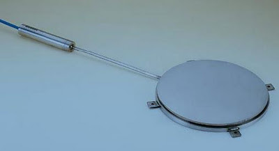
2.4 INSTALLATION
Preliminary Tests
It is always wise, before installation commences, to check the cells for proper functioning. Each cell is supplied with a calibration sheet which shows the relationship between readout digits and pressure and also shows the initial no load zero reading. The cell electrical leads (usually the red and black leads) are connected to a readout box and the zero reading given on the sheet is now compared to a current zero reading. The two readings should not differ by more than ≈50 digits after due regard to corrections made for different temperatures, barometric pressures and height above sea level and actual cell position (whether standing up or laying down). By pressing on the cell it should be possible to change the readout digits, causing them to fall as the pressure is increased. Checks of electrical continuity can also be made using an ohmmeter. Resistance between the
gage leads should be approximately 180 ohms, ± 5%. Remember to add
cable resistance when checking (22 AWG stranded copper leads are
approx-imately 14.7Ω/1000' or 48.5Ω/km, multiply by 2 for both
directions). Between the green and white should be approx-imately 3000
ohms at 25° and between any conductor and the shield should exce-ed 20 megohm.
2.5 Pressure Cell Installation
Installation of Earth Pressure Cells Inside Fills & Embankments
 This section details installation instructions for the Earth Pressure Cell for the measurement of total stress in earth or rock fills and embankments. These procedures are only for cells totally surrounded by earth. Where contact stresses between earth and a structure are
required. Earth pressure cells are normally installed with the flat surfaces horizontal to measure vertical stresses.
However, they can be placed at other orientations, inside the fill, to measure stresses in other directions i.e. a cell placed with the flat surfaces vertical will measure horizontal stresses in a direction perpendicular to the plates of the cell. The position and orientation of the cells can be maintained during installation by means of plywood templates. These templates can be removed by hand after the sand or fine materials immediately surrounding the cells have been placed and carefully hand-compacted.
When installing the cells it is important to avoid direct contact with large rocks. Such contact could locally deform the plates to such an extent that the two plates are pinched together so that the external pressure is no longer transmitted entirely to the interior fluid. For this reason, all chunks larger than 10 mm (≈0.5") should be removed from the material immediately surrounding the cell. It is preferable to surround the cell using the material of the fill rather than another material (e.g. sand) since the stiffness, if the compaction is performed properly, will conform better to the rest of the fill. In areas containing appreciable coarse material, the lenses of fine material should be enclosed in transitional layers of successively coarser material in order to establish a graduation outward to the maximum size material.
No comments:
Post a Comment