Foundation, Concrete and Earthquake Engineering

What is Low Hydrogen Welding Electrodes?

In AWS A5.1, the electrodes listed include both low hydrogen and non-low hydrogen electrodes. In AWS D1.1-96, Group I steels may be welded with non-low hydrogen electrodes. This would include A36 steel. For Group II steels and higher, low hydrogen electrodes are required. These steels would include A572 grade 50. That means for welding on steels with minimum specified yield strengths exceeding 50 ksi, all electrodes should be of the low hydrogen type with specific coatings that are designed to be extremely low in moisture. Water, or H2O, will break down into its components hydrogen and oxygen under the intensity of the arc. This hydrogen can then enter into the weld deposit and may lead to unacceptable weld heat affected zone cracking under certain conditions. Low hydrogen electrodes have coatings comprised of materials that are very low in hydrogen.
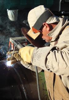
Pipe line Welding with Low Hydrogen Welding Electrode
Low Hydrogen Welding Electrode
The low hydrogen electrodes that fit into the A5.1 classification include E7015, E7016, E7018, and E7028.
SI
NO.
Electrode
Classification
Properties
1.
E7015
Operate on DC only
2.
E7016
Operate on either AC or DC
3.
E7018
Operate on AC or DC and include approximately 25% iron powder in their coatings; this increases the rate at which metal may be deposited
4.
E7028
Contains approximately 50% iron powder in the coating, enabling it to deposit metal at even higher rates. However, this electrode is suitable for flat and horizontal welding only.

vertical up welding with Low Hydrogen Welding Electrode
vertical-up welding with Low Hydrogen Welding Electrode

For most structural steel fabrication today, low hydrogen electrodes are prescribed to offer additional assurance against hydrogen induced cracking. When low hydrogen electrodes are used, the required levels of pre heat are actually lower, offering additional economic advantages to the contractor.

All the low hydrogen electrodes listed in AWS A5.1 have minimum specified notch toughnesses of at least 20 ft. lb. at 0°F. There are electrode classifications that have no notch toughness requirements (such as E6012, E6013, E6014, E7024) but these are not low hydrogen electrodes. Although there is no direct correlation between the low hydrogen nature of various electrodes and notch toughness requirements, in the case of SMAW electrodes in A5.1, the low hydrogen electrodes all have minimum notch toughness requirements.
How does Ultraviolet Light Disinfect Water?

Ultraviolet light has shorter wavelengths than visible light. The light from such electromagnetic radiation can be separated into various ranges:

1.      UVC-UV of short range considered “germicidal UV”.

2.      UVB-UV of longer wavelength considered harmful for human, such as sunburn or sun glare.

At certain wavelengths UV is mutagenic to bacteria, viruses and other micro organisms. At a wavelength of 2,537 Angstroms (254 nm) UV will break the molecular bonds within micro-organismal DNA, producing thymine dimers in their DNA thereby destroying them, rendering them harmless or prohibiting growth and reproduction.


Ultraviolet Lamp from RadiumMicro-organisms have less protection from UV and cannot survive prolonged exposure to it. Ultraviolet germicidal irradiation system is designed to expose environments such as water tanks, sealed rooms and forced air systems to germicidal UV. 


Exposure comes from germicidal lamps that emit germicidal UV electromagnetic radiation at the correct wavelength, thus irradiating the environment. The forced flow of air or water through this environment ensures the exposure.

Features of Ultraviolet Disinfection Module

UV disinfection Module is equipment that achieves an inactivation in germ rate of more than 99.9%, installed in filling equipment for milk products and drinks, for the disinfection of conveyor belts, transport containers. The equipment achieves an inactivation in germ rate of more than 99.9%. 

The immersion lamp consists of a UV low pressure lamp together with a starter, sealed into a water-tight protective quartz tube and fitted with a waterproofed lead. The lamps may be used directly in the water in either a vertical or horizontal position.

The effective penetration depth of the UVC radiation in clear water is 30 to 50 cm. Depending on the length of the immersion lamp, a cylindrical volume of 60 to 100 cm diameter and 20 to 80 cm length can be disinfected in a few minutes.
Ultraviolet Lamp from RadiumDisinfection Modules are ready-to-use build-in systems consisting of:
 
· One or more UV cassettes, window size: length 365 mm
-1315 mm x width of 107 mm - 370 mm at an electrical power of 140 W-1000 W
· UV low pressure lamp
· Forced air cooling using ambient air
· Power supply 50/60Hz, 230 V + 15%
· Quartz glass panes equipped with a breakage detector
· CE-certification
· International Protection Class IP 55 
Ultraviolet Germicidal Irradiation Module
Advantages of the UV Disinfection Modules:
 
· Cold, intense UV radiation
· No chemicals required
· High disinfection rate in just a few seconds
· Low operating costs
· Simple retro-fitting in existing machines
· Breakage detector as part of your HACCP concept
· Easy monitoring of the disinfecting irradiation using a DIC measuring instrument as part of its DIN ISO 9001 quality management system

Ultraviolet Irradiation as Disinfectant

Ultraviolet irradiation is a disinfection technique which break down microorganisms with the use of ultraviolet (UV) light at sufficiently short wavelength. . It was primarily in medical sanitation and sterile work facilities. Now it is Increasingly employed to sterilize drinking and wastewater, as the holding facilities were enclosed and could be circulated to ensure a higher exposure to the UV. In recent years UVGI has found renewed application in air sanitization.

The short wavelength of UV is harmful to microorganisms as it destroy effectively the nucleic acids in these organisms  so that their  DNA is disrupted by  the UV radiation. This removes their reproductive capabilities and kills them.
Ultraviolet irradiation water treatment
Ultraviolet germicidal irradiation module
Such disinfecting effect of the wavelength of UV is rare as its atmosphere blocks it on Earth. Using a UV germicidal irradiation device in certain environments like circulating air or water systems creates a deadly effect on micro-organisms such as pathogens, viruses and molds that are in these environments. Coupled with a filtration system, UVGI can remove harmful micro-organisms from these environments.

Ultraviolet lamp from Radium


Raw waters flow through a chamber where they are exposed to ultraviolet lamps. The resulting disinfection prevents bacterial destruction of cellulose acetate-based membrane systems and eliminates biofouling of polyaromatic-based membrane systems. Because polyaromatic fiber membranes are very susceptible to chemical oxidant attack, ultraviolet disinfection is the best disinfection technique for these systems.

Exterior walls for Steel Building

exterior walls of many forms are used in steel building construction. Walls must be structurally sound, have adequate fire-resistance and insulating properties, offer protection against condensation of water vapor, be durable and easily maintained, and be pleasing in appearance.

Bearing walls must be strong enough to support, in addition to their own weight, any loads from floors and the roof which frame into them. According to the Uniform Building Code, bearing walls of plain masonry must be not less than 12 in thick, except that walls of one-story business buildings and residential buildings not over three stories high may be 8 in thick. Each successive 35-ft height of wall below the topmost 35 ft must be increased 4 in. in thickness. The minimum thickness of unreinforced, grouted. Brick masonry walls may be 2 in less than that required for plain masonry walls. 

 Metal curtain wallSimilar, but less severe, limitations are prescribed for reinforced-concrete bearing walls. Panel walls (also called curtain walls) in skeleton frame construction are usually specified in terms of their fire  -  resistance rating. 
 
metal building system with masonry wall claddingGlass block
ddddddFor example, the BOCA National Building Code requires that the fire-resistance rating of panel walls be not less than 4 h for both fireproof and semi fireproof construction.Except for reinforced-concrete walls, this requirement necessitates masonry walls ranging in thickness from 8 to 12 in.

Glass block in exterior wall of steel building
Corrugated cement-asbestos board and corrugated-metal siding are used extensively for walls of industrial buildings. Wall sections consisting of two steel sheets with a layer of insulation between have also been widely accepted. Very attractive architectural effects are produced with fluted metal wall panels, which may be aluminum, stainless steel, galvanized copper-bearing steel, or porcelain-enameled iron or steel. 
Corrugated asbestos cement board

Structural glass blocks, which are hollow, colorless, and translucent, are appropriate for exterior walls when ventilating sash are not required or when clear glass is not needed for visibility. Since their coefficient of heat transfer is less than one-half that of single-thickness common glass, heating costs are reduced and air conditioning improved. Glass blocks should not be subjected to vertical loads other than their own weight.

What is Ductility?

In case of elastic deformations, a building experiences deformations as force is applied and returning to its original shape when removed. However, extreme earthquake forces may generate inelastic deformations in which the element does not return to its original shape after the force is removed. Ductility is the property of certain elements that have inelastic deformation before failing. Building elements constructed with ductile materials have a "reserve capacity" to resist earthquake overloads. Therefore, buildings constructed of ductile elements, such as steel and adequately reinforced concrete, tend to withstand earthquakes much better than those constructed of brittle materials such as unreinforced masonry.
Ductility in relation to Earthquake

Soil Site Classification According to FEMA

Seismic hazard due to ground shaking can be estimated (According to FEMA 310 and FEMA 368 NEHRP Recommendation) by analyzing the location of the building with respect to causative faults, the regional and site-specific geologic characteristics, and a selected Earthquake Hazard Level. 

However, other seismic hazards could exist at the building site that could damage the building regardless of its ability to resist ground shaking. These hazards include fault rupture, liquefaction or otherc shaking-induced soil failures, landslides, and inundation from offsite effects such as dam failure or tsunami.
liquefaction
SI NO
Soil Site Classification
Description
1
Site class A

Hard rock with measured shear wave velocity greater than 5,000 ft/sec.

2
Site class B

Rock with shear wave velocity between 2,500 and 5,000 ft/sec

3
Site class C

Very dense soil or soft rock [velocity between 1,200 and 2,500 ft/sec]

4
Site class D
Stiff soil [velocity between 600 and 1,200 ft/sec]
5
Site class E
Soil profile with velocity less than 600 ft/sec
6
Site class F
Soils require site-specific evaluations [liquefiable, peats, high plasticity, or very thick soft/medium clays.

Handling and Storage of Fibre-Reinforced Polymer Composites Materials

FRPC system materials including adhesives and resins shall be used in order of manufacture. They shall be stored in dry conditions not exposed to direct sunlight, in strict accordance with the material manufacturer’s data sheet requirements and within the manufacturer’s specified maximum and minimum temperature range. Materials shall remain in their original, sealed containers until time of use. 

All material shall be brought to site in the original unopened cans clearly labelled with the appropriate manufacturer’s name, product type, reference number and batch number. Materials stored beyond the manufacturers recommended shelf life shall not be used. 
FRP wrap concrete beamFRPC plates, laminates or strips shall be supplied and stored on site such that damage or contamination does not occur. Plates, laminates and strips shall be free from unintended curves, bows, wraps, undulations or twists.


Plates, laminates and strips shall be handled with clean gloves under dry conditions, and touching of ready for bonding surfaces without peel ply shall be avoided. Where FRPC materials are fitted with protective peel ply to ensure a clean surface, the ply shall be removed immediately prior to application and touching of the surface shall be avoided.
Typologies of fibre-reinforced composite materials
FRPC fabric sheets or rolls shall be kept free from any contamination. The FRPC fabric sheets shall be handled carefully and shall be free from wraps, twists or fibre misalignment. Any protective peel ply shall be removed immediately prior to application. They shall be stored either by being rolled to a radius greater than 300 mm or by being dry stacked after cutting and shall be protected from dust and moisture.

Handling and preparation precautions shall be in accordance with the material manufacturer’s recommendations and material data sheets. The Contractor shall maintain records showing which elements were treated with each batch of FRPC system material.

The Contractor shall provide, for each batch of FRPC system material, a copy of the manufacturer’s information as specified below:

(a) Manufacturer’s name and address;

(b) Product reference;

(c) Batch number of identification;

(d) Quantity manufactured in the batch; and Certificate of date of manufacture

Micropiles Setup Sequence

Small diameter drilled and grouted friction piles are Micropiles. Each pile includes steel elements that are bonded into the bearing soil or rock – usually with cement grout. The bearing stratum is logged during installation drilling to assure that bearing capacity is adequate. Micropiles do not rely on end-bearing capacity, so there is no need to establish the competency of rock beyond bond-depth. They can be installed quickly in virtually every type of ground using highly adaptable mobile drilling equipment. These steel piles have working capacities up to 250 tons.


Usually foundation engineers use micropiles (minipiles) as an economical alternative to large diameter drilled shaft foundations, especially in difficult ground conditions, karst geology, or restricted access situations.
  Micropiles Setup Sequence:

-Drilled into bedrock, micropiles or minipiles bond to the rock socket wall for load transfer.


-The casings of the minipiles are advanced as piles are drilled into site's bedrock.


-Drill pipe is removed, which leaves casing for mini or micro piles setting in bedrock.


-A reinforcement load bar is lowered into casings of the micro piles, for added capacity.


 -Cementitious grout is pumped or pressure feed into the minipiles casings, bottom up.


-The casings for the micro piles are lifted 
to top of bedrock, allows bonding to the bar.

-Excess steel is cut from the tops of micropiles; piles are capped to engineer's design.


-A select number of piles are load tested to prove the engineering load design.

Spectrum for Polyurethane Grout Applications

Wherever concrete has to be sealed, polyurethanes are the first choice. The spectrum for PU-grout applications is extremely wide. It includes residential work such as leaky basement repair, sealing of pools and concrete balconies and countless applications in commercial areas such as tunnels, bridges and parking garages. Cracks in below grade walls are injected, and liquid membranes behind walls are created with polyurethanes by curtain injection. Drinking and wastewater tanks are being sealed as well as leaky manholes and pipes.


The injection can be done from the negative-side without digging and without access to the waterside. Polyurethanes work in the crack and behind the structure where they create a reliable barrier to prevent further water intrusion. In combination with packers, inject pipes and inject-tubes, grouts offer a dimension of applications unmatched by any other injection material.

Axial Capacity of Pile

When the soil at and near the ground surface is not capable of supporting a structure, deep foundation are required to transfer the load to deeper strata. Pile foundation is such type deep foundation mostly used all over the world. A pile is either driven into soil or formed in-situ by excavating a hole and filling it with concrete.

When a pile is fully embedded in soil with undrained shear strength greater than 10  KN/m2 , the axial carrying capacity of it should not  be limited by its strength as long column. If the soil is weak ( undrained shear strength less than 10 KN/m2), it should be examine whether the shaft would behave as a long column.
Where buckling may occur, its structural strength should be decreased to account for reduction in capacity. In such case, in determining effective length of a pile which is not safe against buckling by adequate bracing, the fixity condition imposed on it by the structure it supports and by the nature of soil in which it is installed, is used. 
 

Oil Well drilling techniques

Oil has gained the reputation of having become one of the most precious commodities that has been found on earth. Nations which possess this valuable reserve have become the most powerful and wealthy in this world and in other words really rule the world economy. This wonder commodity has become an irreplaceable thing whether it is utilized for the industrial applications or for the domestic purposes.

Most of the countries the world over in the past used to depend very much on the crude oil that was being imported from foreign countries mainly from the gulf regions. As a result these countries had to pay huge amounts that were needed for shipping the oil to their respective regions. With the development of the modern technology almost all the countries in this world have taken up the work of exploring for the untapped oil reserves within their geographical boundaries. 
Comparision between horizontal drilling and conventional drilling (horizontal drilling can extract more as it can run along the mineral bearing strutum)
In this endeavor most of the countries have really succeeded well enough with the discovery of huge oil reserves. This made them self sufficient for meeting their own home needs of crude oil and in many cases they had surplus amounts of crude which they could export to other oil needing countries and gain the foreign exchange.
Horizontal drilling reaching oil bearing stratum
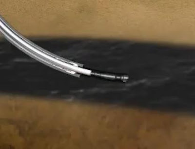
Oil wells were regarded as the wealth of any nation and the amount of oil that was drilled out from these oil wells started to decrease with the course of time. Thus the modern scientific community has made huge technological advances in the refinement of the drilling techniques that was followed in the past. The oil well drilling methods that were used in the past involved the conventional drilling method which was called as the percussion method. This method was being widely followed in almost all the oil wells across the world. In this oil well drilling technique the earth's surface is penetrated by means of a very heavy tool that drills out the oil through the hole. The greatest disadvantage of this method was that, this process was a really slow and time consuming process and the drilling had to be occasionally stopped. There are numerous oil wells and gas wells across the world and several best producing oil wells for sale are listed here.

In the case of the modern drilling methods the oil well drillers use the horizontal drilling method, which was found to be a very effective method when compared to the conventional drilling method that was used till now. The greatest advantage of this method was that the wells that were drilled by the horizontal drilling had larger surface area which in turn made the oil well to be highly productive.

These modern drilling techniques have ensured the oil drilling and exploration companies to reach out the pockets of oil reserves that are located far away from the drill site. As a result of this the oil drilling companies are able to reach out the oil pockets that are located near the heavily populated areas without causing any sort of disturbance to the people over there or to the environment of that particular locality. Hence it can be said that the modern drilling techniques have become a boon to the oil drilling companies.

Seismic Ground Acceleration

A series of vibrations are created when seismic waves move through the ground. These movements are transmitted into dynamic loads or inertial forces that cause the ground and any thing attached to it (i.e., the built environment) to vibrate in a complex manner. These inertial forces cause damage to buildings and other structures. Inertial forces are created when an outside force tries to make an object move or change its rate of travel.

Acceleration is the rate of change of motion. The variation of ground acceleration with time recorded at a point on ground during an earthquake is called an accelerogram. The nature of accelerogram may vary depending on
 
- Energy released at source

- Type of slip at fault surface

- Geology along the travel path from fault rupture to the earth surface

- Local soil


They carry distinct information regarding ground shaking; peak amplitude, duration of strong shaking, frequency content ( amplitude of shaking associated with each frequency) and energy content (i.e., energy carried by ground shaking at each frequency) are often used to distinguish them.


Normally acceleration is not associated with buildings since building is not expected to move. During an earthquake, however, inertial forces may cause the upper part of the building to sway while the foundation remain stationary, or they may cause whole building to “move”. Structures built in seismically active areas must be built to withstand predicted acceleration levels.

claim token

TJNUATNSJ44B

Simplification of Building Frame Considering Sub Frames

For building frames with reasonably regular outline, not involving unusual asymmetry of loading or shape, the influence of side sway caused by vertical loads can be neglected. In the case, moments due to vertical loads are determined with sufficient accuracy by dividing the entire frame into simpler sub frames. Each of these consists of one continuous beam, plus the top and bottom columns framing into that particular beam. Placing the live loads on the beam in the most unfavorable manner permits sufficiently accurate determination of all beam moments, as well as the moments at the top ends of bottom columns and at the bottom ends of the top columns. For this partial structure, the far ends of the columns are considered fixed, except for such first floor or basement columns where soil and foundation conditions dictate the assumption of hinged ends.

ACI 8.9

The live loads may be considered to be supplied only to the floor or roof under consideration and the far ends of the columns may be assumed as fixed. When investigating the maximum negative moment at any joint, negligible error will result if the joints second removed in each direction are considered to be completely fixed. Similarly, in determining maximum or minimum span moments, the joints at the far ends of the adjacent spans may be considered fixed. Thus individual portions of a frame of many members may be investigated separately.

In regards to columns, the ACI code indicates :


ACI 8.9

a) Columns shall be designed to resist the axial forces from loads on all floor and the maximum bending due to design loads on a single adjacent span of the floor under consideration. Account shall be taken of the loading condition giving the maximum ratio of the bending moment to axial load.


b) In frames or continuous construction, consideration shall be given to the effect of unbalanced floor or roof loads on both exterior and interior columns and of eccentric loading due to other causes.


c) In computing moments in columns due to gravity loading, the far ends of columns built integrally with the structure may be considered fixed.


d) The resistance to moments at any floor or roof level shall be provided by distributing the moment between columns immediately above and below the given floor in proportion to the relative column stiffness and conditions of restraint.

Washington DC Plumbing - Home Saviours

Plumbing solutions are perhaps the most sought after in terms of what people need in their homes. The need for a good plumbing provider is something most people are looking at. Everyone is more aware today, and is looking for a good relationship with plumbers not just when the emergency strikes, but well before it. Aware that the need for them is constant, and that an emergency requires quick actions, most people look to avail ofplumbing assistance that can take care of all their problems, and also be available to them as and when they may be needed.
For a city which is so large and has a population which is sizable, Washington DC plumbing is almost a universe of its own. With solutions that are varied and available at all locations you can think of, there is no place inWashington DC which is untouched by great plumbing solution providers. This has allowed all people access to good plumbing facilities, and also the possibility of having all emergencies taken care of with greater immediacy.
Emergency Commercial Plumbing Vehicle
There are various needs that prompt the use of plumbers. No longer are they only called in for leaks and broken pipes. Today, plumbers are called in for the installation of heaters and heating facilities, for the renovation of all pipes and fittings, and also to take care of leaks and seepages. Additionally, they also make great consultants who will be able to guide you through the best ways of caring for yourplumbing , and also to detect any faults in the pipes and amenities. Several people have contracts with plumbers who will come in for routine checks and take a look at all your fittings to make sure they are in order.
Resolving bathroom faucet,Washington, D.C
Even with checks, there are bound to be emergencies that arise at some times. This is when special services come in handy. Of the various Washington DC plumbing solutions, many come with the assurance of being available round the clock. This makes them easier to access, and also allows you the security of having things taken care of no matter when they occur. Coming in to your house in very short response, they take over immediately and bring things under control quickly before things turn disastrous for you.
Plumbers are more of an investment today, the key to a sound, smoothly functioning house. A trusted plumber is not just a valuable resource, but someone you can trust your house to. You will find that when you have a greatWashington DC plumbing provider, your house will have a more secure feel instantly.

Tips for Foundation Engineers to Found on Black Cotton Soil

Atmospheric conditions induce volumetric changes in black cotton soil due to presence of fine clay particles in it. These ground movement on account of swelling and shrinkage causes severe cracking and foundations rested on such soil fall in great danger. Some tips found useful, derived from several experiment and experiences from many years, are listed below:

1. To provide reinforced concrete ties or bands all around the main walls of the building. The R.C.C ties or bands which may be 10 cm to 15 cm deep should be placed at plinth level, lintel level and eaves level. In case of flat roof, R.C.C slab it self acts as a tie and as such no extra band needed to be provide near the roof in such cases.

2. If the depth of the black cotton soil at a given site is only 1 to 1.5 m, the entire black cotton soil above the hard bed may be completely removed and the foundation may be laid on the hard bed below.
Removal of Black-Cotton Soil from Sub-grade 3. To limit the load on the soil to 5.5 tonnes/ sqr. m. if water is liable to to find an access to the foundations, the limit of loading should be restricted to 4,900 kg/ sqr. m.


4. To take the foundation to such depths where the cracks cease to extend. The minimum depth of foundation should be at least 1.5 m.


5. The swelling of soil in direct contact with the foundation material causes maximum damage. Hence it is necessary to prevent the direct contact of black cotton soil with masonry work below ground level. These can be achieved by making wider trenches for foundation and filling spaces on the either side of the foundation masonry with sand or moorum.
Removal of Black-Cotton Soil from Entire Site

6. The bed of foundation trench should be made firm or hard by ramming it well. On the rammed bed a 30 cm layer of good hard moorum should be spread in layers of 15 cm, each layer being well watered and rammed before laying the next layer. On this layer either stone or sand bed should be provided to the desire height to place the foundation concrete bed block upon it.
Removing Top Black Cotton Soil Layer for Foundation of Filling Station in Francistown
7. In case of ordinary buildings, the foundation should be taken at least 30 cm deeper than the depth where the crack stop.


8. In important structures raft foundation should be provided so as to float the building on the bed below the depth, quite independent of the surrounding soil.


9. For less important structures like compound walls etc., the foundation should preferably be taken at least 15 cm below the depth at which cracks in soil cease to occur.


10. Construction in black cotton soil should be undertaken during dry season.


11. The masonry for the walls should start at least 15 cm below the general ground level.


12. The width of trench for main walls or load bearing walls of a building should be dug 40 cm wider than the width of foundation. This is necessary to ensure provision of at least 20 cm wide layer of coarse sand on either side of foundation masonry thereby separating the sub-structure from having direct contact with black cotton soil. In case of compound wall, width of sand layer on either side of foundation masonry could be 15 cm.

SBR Latex in Construction:A Guide

SBR (Styrene Butadiene Rubber) latex is fighting against:
- polyacrylic esters (PAE) and
- styrene acrylic esters (SA)
to increase it’s market share in the polymer modified concrete industry. In this fight, we consider SBR latex the winner hands down, if we take account of both cost and performance.

In Europe we mostly use carboxylated SBRs with:

- solid contents in the region of 47-49%.

- minimum film forming temperatures round 0-3oC.

- glass transition temperatures round -5oC.


Usually they contain antifoam and antimicrobial agents.


SBR Latex modified, flexible cementitious   coating to cover non-structural surface   defects in new and old concrete.
SBR Latex modified, flexible cementitious 
coating to cover non-structural surface
 defects in new and old concrete.
MAIN ADVANTAGES OF POLYMER MODIFIED CEMENT MIXES
- Improved flexural and tensile strengths
- Better overall durability

- Reduced shrinkage

- Increased resistance to abrasion, chemicals and frost
- Improved workability for the same W/C

- Enhanced adhesion to smooth surfaces: dense concrete, steel etc.

- Suitable for potable water

- Resistant to hydrolysis.

self-leveling industrial floor materials with synthetic latex
MAIN APPLICATIONS IN EUROPE (AND GREECE)
- Amelioration of cementitious waterproofing products and tile adhesives.

- Thin, water resisting screeds, toppings, renderings, mortars etc.

- Waterproof, bonding bridges for mortars and concrete (always mixed with fresh cement and always wet on wet). Mixing proportion: 1:1,8 latex/cement by volume.

- Anticorrosion protection for reinforcements in concrete repairs (1:1 with cement by volume).

- Polymer mortars for repairs of carbonated concrete. Preventive treatments against carbonation.


SBR latex; Styrene Butadiene Latex

SBR latex; Styrene Butadiene Latex

ACTION MECHANISMS OF SBR LATEX

1) SBR can reduce W/C for the same workability or increase workability for the same W/C. Polymer particles as well as entrained air bubbles have a ball bearing effect in the mixture. They “lubricate” the mixture particles thus reducing internal friction coefficient.

Workability improvement is further enhanced by the dispersion capabilities of the contained surfactants.

2) SBR latex due to its air entraining properties reduces bleeding considerably. This leads to an abrasion resistant surface. Though, excessive air entrainement should be avoided and most probably an antifoam agent should be used in the formula. Prolonged mixing duration entrains more air.


3) SBR latex used in cementitious waterproofing brushable products improves dramatically their water retention capability. This is a most desirable effect leading to a better hydration procedure. This water retention improvement is due to the polymer network that somehow blocks the water in the mixture.

4) SBR addition increases the water resisting properties of modified concrete and mortars.

As water evaporates, the SBR particles stick together – this is called coalescence – to form an interconnected polymer network inside the cementitious matrix. This flexible network both blocks the pores and bridges microcracks to a certain extend. Less and thinner cracks and less voids increase water impermeability.


5) SBR latex increases adhesion of aggregates to cement paste. It also enhances adhesion of cement mixes to smooth substrates: dense concrete, steel etc. This is due to the powerful bonding power of the polymer matrix.


EFFECTS OF SBR ADDITION ON PROPERTIES OF CEMENT MIXES

1. Increases tensile, flexural and impact strengths. Compressive strength remains virtually unaltered. In high dosages it could slightly decrease.
2. Overall durability increases.
3. Induced flexibility increases creep.
4. Setting times are generally reduced. Placement time also.
5. SBR addition reduces bleeding and contributes to an enhanced abrasion resistance provided that an adequate curing procedure is followed.
6. SBR latex addition increases air entrainement (despite the antifoam agent in the formula).

Followers