Foundation, Concrete and Earthquake Engineering

Seismic Shake Map and Intensity of Quake

Geographic representation of seismic Ground shaking is Shake Map. Intensity is one of the ways that ground shaking is expressed, along with more quantitative measures like velocity and acceleration. The information Shake Map presents is different from the earthquake magnitude. Magnitude is the number that represents the energy released in an earthquake; a single number representing magnitude is assigned to each earthquake. Intensity, on the other hand, is a measure of how the ground shook at a particular site. So, while an earthquake has one magnitude and one epicenter, it produces a range of ground shaking levels at sites throughout the region.

M 9.0 - HONSHU MEGA THRUST

These different intensities depend on distance from the earthquake, the rock and soil conditions at geographical sites, and variations in the propagation of seismic waves from the earthquake due to complexities in the structure of the Earth's crust. Shake Map focuses on the ground shaking produced by the earthquake, rather than the characteristics of the earthquake source.

Special Design Provision for Soft First Storey

To safeguard the soft first storey from damage and collapse code provides two alternative design approaches:


1) The dynamic analysis of the building is to be carried out which should include the strength and stiffness effects of infills as well as the inelastic deformations under the design earthquake force disregarding the reduction factor R.


2) The  building  is  analyzed  as  a  bare  frame  neglecting  the  effect of   infills   and,   the   dynamic forces  so  determined  in columns   and   beams   of  the   soft (stilt)  storey are to be designed for 2.5 times the storey shear and moments:

or the shear walls are introduced in the stilt storey in both directions of the building which should be designed for 1.5 times the calculated storey shear forces.

Consideration for Hot Weather Concreting

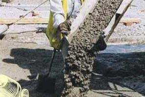
The main things to consider during hot weather concreting are:

a) minimising the early loss of water from concrete;

b) preventing early setting through too-rapid drying.

If these problems are not anticipated, there may be:
• Strength reduction
• Shrinkage cracks
• Crazing or cracking

• Finishing difficulties.

In very hot conditions the following steps should be undertaken:

• Thoroughly moisten the sub-grade, reinforcing steel and wooden forms before placing the concrete.

• Avoid delay in placing the concrete. Have sufficient labour and equipment on hand to perform the placing
quickly.

• During placement in very hot weather, try to shade the concrete from direct sunlight.

• Use wet coverings until final finishing can be completed.
• If a float finish is required, uncover only a small section immediately ahead of the finishers.
Cover again at once after final finish.

• Keep covers wet.

• Start curing as soon as possible, using a method that will keep temperature of the covered concrete at or
about a constant 21ºC.

• Discharge concrete from waiting trucks as soon as possible. Heat builds up in mixer drums if this is not done.

• In very hot weather shade concrete from sunlight or use wet coverings until finishing can be completed.

Foundation on Sloping ground

a) In case of footing on sloping ground, the distance of the sloping surface at the base level of the footing measured from the center of footing shall not be less than twice the width of the footing.

       ds ≥ 2 x w

Where,

ds = distance from center of footing to sloping surface at base level.

W = width of footing.

L = length of footing

Moreover, the minimum distance from the lower edge of the footing to the sloping ground surface should be 90 cm.
Foundation on Sloping ground
b) in case of footings which are in different levels, the distance between the edges of footing shall be such as to prevent undesirable overlapping of structures in soil and disturbance of soil under the higher footing due to excavation of the lower footing.
Foundation on Sloping ground
c) On a sloping site, footing shall be on a horizontal bearing and stepped. At all changes of levels, footing shall be lapped for a distance of at least equal to the thickness of foundation or three times the height of step, whichever is greater. Adequate precaution shall be taken to prevent tendency for the upper layers of soil to move downhill.
Foundation on Sloping ground                           
                 dl ≥ t

   *                dl ≥ 3 x hs

Where, dl = lapped distance of footing at changes in level.

t = thickness of footing

hs = height of step

The greater value is considered in design.

Seismic Peak Acceleration Maps

Peak horizontal acceleration at each station is contoured in units of percent-g (where g = acceleration due to the force of gravity = 981 cm/s/s). The peak values of the vertical components are not used in the construction of the maps because they are, on average, lower than the horizontal amplitudes and ground motion prediciton equations used to fill in data gaps between stations are based on peak horizontal amplitudes. The contour interval varies greatly and is based on the maximum recorded value over the network for each event.

Maps - General Information

  • The Red star usually located near the center of the map is the epicenter.
  • Small unfilled circles, shown on some maps, are points where strong motion values were estimated and used to fill gaps in the station distribution.Seismic Peak Acceleration Maps
  • The colored triangles indicate reporting stations. In California, for example:
    a)   Red triangles are stations from the Caltech/USGS digital telemetered network.
    b) Blue triangles represent California Geological Survey (CGS) and California Strong Motion Instrumentation Program (CSMIP) dial-up stations.
    c)   Yellow triangles represent stations from the ANZA Regional Network.
    Green triangles represent National Strong Motion Project (NSMP) dial-up stations or, on historical maps, non-digital stations from which strong motion records were digitized
    Contour  of Peak Ground Acceleration of Honshu Mega Thrust: Fraction of Contour is: 
    >90 contour
    140.969 38.3694 90
    141.002 38.3768 90
    141.019 38.3637 90
    141.036 38.3429 90
    141.043 38.3303 90
    141.036 38.3105 90
    141.03 38.297 90
    141.002 38.2639 90
    141.002 38.2637 90
    140.969 38.2404 90
    140.946 38.2303 90
    140.936 38.2262 90
    140.927 38.2303 90
    140.902 38.2522 90
    140.895 38.2637 90
    140.902 38.2831 90
    140.908 38.297 90
    140.929 38.3303 90
    140.936 38.3384 90
    140.962 38.3637 90
    140.969 38.3694 90
    >90 contour
    140.636 36.6435 90
    140.655 36.6303 90
    140.669 36.6077 90
    140.673 36.597 90
    140.669 36.5905 90
    140.641 36.5637 90
    140.636 36.5604 90
    140.628 36.5637 90
    140.602 36.5792 90
    140.588 36.597 90
    140.602 36.6205 90
    140.612 36.6303 90
    140.636 36.6435 90
    >120 contour
    141.036 38.7741 120
    141.054 38.7637 120
    141.069 38.7503 120
    141.082 38.7303 120
    141.069 38.7036 120
    141.064 38.697 120
    141.036 38.678 120
    141.004 38.697 120
    141.002 38.6983 120
    140.985 38.7303 120
    141.002 38.7536 120
    141.015 38.7637 120
    141.036 38.7741 120

For moderate to large events, the pattern of peak ground acceleration is typically quite complicated, with extreme variability over distances of a few km. This is attributed to the small scale geological differences near the sites that can significantly change the high-frequency acceleration amplitude and waveform character. Although distance to the causative fault clearly dominates the pattern, there are often exceptions, due to local focussing and amplification. This makes interpolation of ground motions at one site to a nearby neighbor somewhat risky. Peak acceleration pattern usually reflects what is felt from low levels of shaking up to to moderate levels of damage.

Jack Pile Underpinning

Jack  Pile  Underpinning  method  can  be  used  when  the  depth  of  a suitable bearing  capacity subsoil is too deep to make traditional underpinning uneconomic. Jack pile underpinning is quiet, vibration free and flexible since the pile depth can be adjusted to suit subsoil conditions encountered. 


The existing foundations must be in a good condition since they will have to span over the heads of the pile caps which are cast onto the jack pile heads after the hydraulic jacks have been removed. 
Jack Pile Underpinning

Application of superplasticizers

Superplasticizers provide revolution on the use of concrete in a number of ways, making it possible to place it, and to do so easily, where it is not possible to do so before. Superplasticizers make it also possible to produce concrete with significantly superior strength and other properties, now termed high performance concrete.


Superplasticizers do not significantly affect the setting time of concrete except that, when used with cement having a very low C3A content, there may be excessive retardation.
They can be successfully used in concrete containing fly ash and are particularly valuable when silica fume is present in the mix because that material increases the water demand of the mix. However, if re-dosage is necessary, the quantity of the superplasticizer required is larger than when the concrete contains no silica fume.
SUPER PLASTICIZER
AC-MENT-BV-430-A2: Super Plasticizer for PC. Base
 
AC-MENT-BV-430-A3: Super Plasticizer for pumpable
 concrete on PC Base 
AC-MENT-BV-430-E6:High range Super Plasticizer on
 modified basis for pumpable concrete
Superplasticizers do not influence shrinkage, creep, modulus of elasticity or resistance to freezing and thawing. They have no effect on the durability of concrete. Specifically, durability on exposure to sulfates is unaffected. The use of superplasticizers with an air-entraining admixture requires caution as sometimes the actual amount of entrained air is reduced by the superplasticizers.
FDN-A, B AND C Superplasticizer is a dry powdered admixture. It is produced through such a process: 1) sulphonating refined naphthalene with sulfuric acid, 2) condensing with formaldehyde, 3) neutralization, and 4) filtering. It conforms to GB8076-1997 and is mainly used for various high-strength concrete, steel concrete, prestressed concrete, large formwork concrete, slipforming concrete etc.

Contact pressure on sand

The soil reaction beneath footing produce a upward pressure which is assumed uniform in deriving different relationship for soil-structure interaction problem. This pressure is called contact pressure. 


Flexible footing
In this case, the edges of flexible footing undergo a large settlement than at the centre. The soil at the centre is confined and, therefore, has a high modulus of elasticity and deflects less for the same contact pressure. The contact pressure is uniform. 

Rigid footing 
If the footing is rigid, the settlement is uniform. The contact pressure increases from zero at the edges to a maximum at the centre. The soil, being unconfined at edges, has low modulus of elasticity. However, if the footing is embedded, there would be finite contact pressure at edges.
Contact pressure on sand
Fig: Qualitative contact pressure distribution under flexible and rigid footing resting on sandy soil and subjected to a uniformly distributed load q.

Numerical Relationship Between Compressive and Tensile Strength of Concrete

It is expected that these two types of strengths are closely related, but there is no direct proportionality. It is noticed that with the increment of compressive strength, the tensile strength is also increased but at a decreasing rate.

A better correlation is found between the various measures of tensile strength and the square root of the compressive strength. A number of empirical formulae connecting ft and fc´ have been suggested, many of them of the following type:

ft = k (fc)n

where k and n are co-efficients. Values of n between ½ and ¾ have been suggested. The former value is used by the American Concrete Institute, but Gardner and Poon found a value near the later, cylinders being used in both cases. Probably the best fit overall is given by the expression:

ft = 0.3 (fc)2/3
where, ft is the splitting strength, and fc´is the compressive strength of cylinders, both in megapascal. If the stress is expressed in pounds per square inch the co-efficient is replaced by 1.7. The above expression was suggested by Raphael. A modification of Oluokun is

ft = 0.2 (fc)0.7

where the strength are in megapascals; the co-efficient becomes 1.4 in psi.

an expression used in British Code of practice BS 8007:1987 is similar, namely

ft = 0.12 (fc)0.7

Bearing in mind that the compressive strength is determined on cubes(in megapascals); ft represents the direct tensile strength.

The difference between the various expressions are not large. What is important, however, is that the power exponent used in the ACI Building Code 318-89( revised 1992) is too low so that the splitting strength is overestimated at low compressive strengths and underestimated at high compressive strength.

These approximate expressions show that tension and compression strength are by no means proportional, and that any increase in compression strength, such as that achieved by lowering the water-cement ration, is accompanied by a much smaller percentage increase in tension strength.

The ACI Code contains the recommendation that the modulus of rupture fr be taken to 7.5 √ fc´for normal weight concrete, and that this value be multiplied by 0.85 for “ sand-lightweight” and .075 for “all-lightweight” concrete giving values of 6.4 √ fc´ and 5.6√ fc´ respectively for those materials. The former refers to light weight concrete containing natural sand for fine aggregate. Linear interpolation may be used for mixtures of natural sand and lightweight weight fine aggregate.

Quick Field Procedures for Soil Identification

The foundation engineers need to classify the site soils for use as a foundation for some important reasons. These reasons are:

1. To be able to use the database of others in predicting foundation performance.

2. To build one's own local database of successes (or any failures).

3. To maintain a permanent record that can be understood by others should problems later develop and outside parties be required to investigate the original design.

4. To be able to contribute to the general body of knowledge in common terminology via journal papers or conference presentations. After all, if one is to partake in the contributions of others, one should be making contributions to the general knowledge base and not be just a "taker."

It is sometimes useful to be able to make a rapid field identification of the site soil for some purpose. This can be done approximately as follows:
 
1. Differentiate gravel and sand by visual inspection.

2. Differentiate fine sand and silt by placing a spoonful of the soil in a deep jar (or test tube) and shaking it to make a suspension. Sand settles out in 1.5 minutes or less whereas silt may take 5 or more minutes. This test may also be used for clay, which takes usually more than 10 minutes. The relative quantities of materials can be obtained by observing the depths of the several materials in the bottom sediment.
3. Differentiate between silt and clay as follows:
 
a. Clay lumps are more difficult to crush using the fingers than silt.
b. Moisten a spot on the soil lump and rub your finger across it. If it is smooth it is clay;
if marginally streaked it is clay with silt; if rough it is silt.

c. Form a plastic ball of the soil material and shake it horizontally by jarring your hand. If the material becomes shiny from water coming to the surface it is silt.

4. Differentiate between organic and inorganic soils by visual inspection for organic material or a smell test for wood or plant decay odor.

Seismic Zoning Map of Pakistan.


Nine Months to Go to Cool Fukushima Daiichi Nuclear Reactors

On Sunday Tepco unveiled its roadmap to control the nuclear crisis as US Secretary of State Hillary Clinton briefly visited Tokyo to pledge America's "steadfast support" for Japan's reconstruction. The operator of Japan's crippled Fukushima Daiichi nuclear plant has said it expects to bring the crisis under control by the end of the year.

Tokyo Electric Power Co (Tepco) aims to reduce radiation leaks in three months and to cool the reactors within nine months. The utility said it also plans to cover the reactor building, which was hit by a huge quake and tsunami on 11 March.


On the other hand, Radiation levels in the sea near reactor 2 rose to 6,500 times the legal limit on Friday, up from 1,100 times a day earlier, Tepco has said, raising fears of fresh radiation leaks.
In response to local government's order to provide specific timetable to end the crisis, Tepco said they would need up to nine months to bring the power plant to ''cold shutdown''. They said the plan would allow the tens of thousands of families evacuated from the area around the facility to return home as soon as possible. Tepco said after cold shutdown it would focus on encasing the reactor buildings, cleaning up contaminated soil and removing nuclear fuel. 

Robots to Go into Fukushima Daiichi Nuclear Reactors

Tsunehisa Katsumata, the chairman of Tepco, Asia's largest utility, said it was sending remote-controlled robots into one of the reactors on Sunday to gauge radiation and temperature levels. UK defence contractor QinetiQ said it had provided the machines, which are controlled using a standard games console.

The robots can carry out tasks such as rubble clearance, demolition and radiation testing. Japan is a world leader in such technology, but its robots are not adapted for dirty work such as meltdowns at nuclear plants.

Seismic Waves Strucking Structures

Whenever the earth is suddenly struck or disturbed  due to earthquake vibration are produced. These vibrations are setup or start from a limited area and are propagated outward in all directions. Thus an earthquake may be defined as the passage of these vibrations in the earth.

Nature, Speed and Penetration Capacity of different Seismic waves were stated in previous posts

when P-waves and S-waves reach the earth's surface, most of their energy is reflected back. Some of the energy is returned back to the surface by reflections at different layers of soil and rock. Shaking is more severe (about twice as much) at the earth's surface than at substantial depths. This is often the basis for designing structures buried underground for similar levels of acceleration than those above the ground.

Deep-Ocean Assessment and Reporting of Tsunami (Dart) System

Seismometers staked out around the ocean can almost instantly pinpoint a quakes location. In the next moment, complex computer programs can predict how long a triggered tsunami would take to reach coastlines, even though there have no yet a evidence of wave exists. After some minutes, tide gauges scattered along coastline may detect tsunami. But the only way to be sure whether a dangerous wave is headed toward a distant coast is to place tsunami detectors in its path and track it across the open ocean. This tsunami detectors is the DART system.

The DART system depends on bottom pressure recorders. As the crest of a tsunami wave passes by, the bottom recorder detects the increased pressure from the additional volume of overlying water.
Even from 6,000 meters depth, the sensitive instrument can detect a tsunami no higher than a single centimeter. Ship and storm waves are not detected, because their length is short and, as with currents, changes in pressure are not transmitted all the way to the ocean bottom.


When the bottom recorders detect a tsunami, acoustic chirps will transmit the measurements to a car size buoy at the ocean surface, which will than relay the information to a ground station via satellite.

More buoys would reduce the possibility that tsunami waves might sneak between them. Combined with the buoy measurements, the simulations of tsunami in computer will provide more accurate predictions to guide officials who may have only a few minutes to decide whether to sound an alarm.

Sulfonated Melamine-Formaldehyde Resin Superplasticizer for Concrete

Sulfonated Melamine-Formaldehyde Resin Superplasticizer is a White Powder having packaging details of 25kg/bag 1fcl=17mt. Concrete High-range Water-reducer SM (Sulfonated Melamine-formaldehyde Resin) is a polymer electrolyte, SM is the best one of existing concrete admixture in comprehensive properties.

It is able to prepare high-strength concrete and flowing concrete by adding SM into Ordinary Portland Cement. For high-strength concrete the compressive strength will reach or surpass 80MPa.This concrete is largely used in high-raise building and many important prestressed concrete structure of civil engineering. The flowing concrete is usually used for in-site casting and pump concreting,such as mass foundation and other structure with closs arranging reinforcement .

It has a excellent compatibility for Aluminous Cement. It metallurgical industry SM is often used as major admixture for refractory concrete, included castables and field mixes.

The product of SM is of a white or transparent colourless water solution. Owing to this it can be extensively used in inorganic decorative materials such as man-made marble,terrazzo,paints and various gypsum products.  


Specification


Item
Standard
Appearance White powder
Surface Tension (71±1)×10N/cm
pH Value 7~9
Na2SO4 content 3.0~4.0%
Cl-content 0.3~0.4%


Technical properties
1.For dosage within 0.5~1.0% by weight of cement,the water reduction rate will be 20~25%
2. When dosage is appropriate , It is able to increase the compressive strength of concrete and mortar by 40~100% at one day,by 30~60% at 28 days . The later age strength also in crease (about 20%) .
3. It is able to prepare high strength concrete (60~80MPa,even higher) by using 45.5#~55.5# Ordinary Portland Cement .
4.Adding SM to refractory concrete,from Aluminous Cement,the strength after drying at 110C and after burning at high temperature will increases obviously(by 60~170% for compressive).
5. Because of no air-entrainment SM can be used curing of concrete and their products.
6. The SM is usually applied for α-hemi hydrate gypsum and β-hemi hydrate gypsum,When dosage is 0.5~1.0% by weight of gypsum,It is able to increase the strength of gypsum by high water-reducing rate.

Steel - Concrete Surface Interaction

For most effective reinforcing action, it is essential that steel and concrete deform together, i.e., that there be a sufficiently strong bond between the two materials so that no relative movements of the steel bars and the surrounding concrete occur. This bond is provided by the relative large chemical adhesion which develops at the steel concrete interface, by the natural roughness of the hot - rolled reinforcing bars and by the closely spaced rib-shaped surface deformations with which reinforcing bars are furnished in order to provide a high degree of interlocking of the two materials.

Additional features related to combined performance of two materials are following:

1) The thermal expansion coefficient of the two materials are

Steel - 0.0000065

Concrete - 0.0000055

These values are sufficiently close to forestall cracking and other undesirable effects differential thermal deformations.

2) While the corrosion resistance of bare steel is poor, the concrete which surrounds the steel reinforcement provides excellent corrosion problems and corresponding maintenance costs.

3) The fire resistance of unprotected steel is impaired by its high thermal conductivity and by the fact that its strength decreases sizably at high temperatures. Conversely the thermal conductivity of concrete is relatively low. Thus damage caused by even prolonged fire exposure, if any, is generally limited to the outer layer of concrete, and a moderate amount of concrete cover provides sufficient thermal insulation for the embedded reinforcement.

Dosage of Superplasticizers

In order to increase the workability of the concrete mix, the normal dosage of superplasticizers is between 1 and 3 litres per cubic metre of concrete, the liquid superplasticizer containing about 40 percent of active material. When superplasticizers are used to reduce the water content of the mix, their dosages is much higher: 5 to 20 litres per cubic metre of concrete. In the calculation of the water/cement ratio and of mix proportions in general, the volume of the liquid superplasticizer must be taken into account. 

It is worth noting that the concentration of solids in commercial superplasticizers varies so that any comparison of performance should be made on the basis of the amount of solids, and not on the total mass. For practical purposes, comparison should be made on the basis of the price for a given effect.
The effectiveness of a given dosage of a superplasticizer depends on the water/cement ratio of the mix. Specifically, at a given dosage of the superplasticizers, the percentage water reduction which maintains a constant workability is much higher at low water/cement ratio of 0.40, the reduction was observed to be 23 percent, and only 11 percent at a water/cement ratio of 0.55.

When superplasticizers are used in very low dosages to produce high workability normal-strength concrete, there are few problems in selecting an admixture-cement combination. At high dosages, the situation is significantly different in that the superplasticizers has to be compatible with the actual cement used, and is not enough for the superplasticizers and the cement separately to conform to their respective standards.  
FDN-A, B AND C Superplasticizer is a dry powdered admixture. It is produced through such a process: 1) sulphonating refined naphthalene with sulfuric acid, 2) condensing with formaldehyde, 3) neutralization, and 4) filtering. It conforms to GB8076-1997 and is mainly used for various high-strength concrete, steel concrete, prestressed concrete, large formwork concrete, slipforming concrete etc.

Consequence of Making Assumptions in Pressure Distribution below Footing

Contact pressure is the upward pressure produced by soil reaction on the underside of the footing.  These soil reaction is assumed uniform in deriving different relationship for soil-structure interaction problem. But actually a footing are not flexible as well as contact pressure is not uniform, necessitating more investigation for actual contact pressure distribution. 
Factor Influencing Contact Pressure

The actual distribution of contact pressure depends upon a number of factors such as

1) Elastic properties of footing

2) Elastic properties of soil

3) Thickness of footing

Different characteristics of contact pressure distribution under flexible and rigid footings are described below:

Contact Pressure On Saturated Clay

Flexible Footing

When a footing is flexible, it deforms into shape of bowel, with the maximum deflection at the center. The contact pressure distribution is uniform.

Rigid Footing

When a footing is rigid, the settlement is uniform. The contact pressure distribution is minimum at the center and the maximum at the edges. The stresses at the edges in real soils can not be infinite as theoretically determined for an elastic mass. In real soils, beyond a certain limiting value of stress, the plastic flow occurs and the pressure becomes finite.

Fig: Qualitative contact pressure distribution under flexible and rigid footing resting on   
saturated clay and subjected to a uniformly distributed load q.


Contact pressure on sand

Flexible footing
In this case, the edges of flexible footing undergo a large settlement than at the centre. The soil at the centre is confined and, therefore, has a high modulus of elasticity and deflects less for the same contact pressure. The contact pressure is uniform. 

Rigid footing
If the footing is rigid, the settlement is uniform. The contact pressure increases from zero at the edges to a maximum at the centre. The soil, being unconfined at edges, has low modulus of elasticity. However, if the footing is embedded, there would be finite contact pressure at edges.
Fig: Qualitative contact pressure distribution under flexible and rigid footing resting on sandy soil and subjected to a uniformly distributed load q.

Thus it is observed that the contact pressure distribution for flexible footing is uniform for both clay and sand. The contact pressure for rigid footing is maximum at the edges for footing on clay, but for rigid footings on sand, it is minimum at the edges.

Consequence of assuming uniformity in pressure

For convenience, the contact pressure is assumed to be uniform for all types of footings and all types of soils if load is symmetric.
The above assumption of uniform pressure distribution will result in a slightly unsafe design for rigid footing on clays, as the maximum bending moment at centre is underestimated. It will give a conservative design for rigid footings on sandy (cohessionless) soils, as the maximum bending moment is overestimated. However, at the ultimate stage just before failure, the soil behaves as an elasto-plastic material ( and not an elastic material) and the contact pressure is uniform and the assumption is justified at the ultimate stage.

What to Do After Tsunami?

These measures should be taken after tsunami :
1) Tsunami waters, as by flood water, can undermine foundation resulting foundation to sink fallowed by collapse of walls and cracking in floor. So, come out of building if water surrounds it.

2) Look for help. If possible help injured or trapped persons. In appropriate case give first aid but do not move seriously injured people as it may cause deteriorating their conditions.

3) Telephone lines are frequently overwhelmed in disaster situations. They need to be clear for emergency calls to get through requiring to make calls on telephone for emergency calls only.
4) The tsunami may have damaged roads, bridges, or other places that may be unsafe to use and keep listening to weather reports, Coast Guard emergency frequency station.

What to Do After Tsunami?
5) Flood water driven by tsunami may have damaged structures. So extreme caution have to take before entering any building.


6) To avoid fire hazard use battery powered lanterns of flash lights to examine your residence.


7) Wear safe shoes to avoid injury associated with cut feet which is common case after such disaster.


8) Look for broken or leaking gas lines, flooded electrical circuits, or submerged furnaces or electrical appliances.


9) Flammable or explosive materials may come from upstream resulting most frequent hazard and keep aware of this.

10) Open a window and leave quickly the building and turn off the gas using the outside main valve, if possible, and call Gas Company. If you smell gas or hear a blowing and hissing noise, without a professional the valve should not open.

What to Do After Tsunami?
11) Electrical equipment should be checked and dried before being returned to service.

12) Inspect electrical system damage. Any spark or broken or frayed wires or smell of burning insulation is a sign of electrical hazard. The main fuse box or circuit breaker should be turned off at once. But, if, to reach their, you have to step in water call an electrician first for advice.


13) Tsunami flood waters flush snakes and animals out of their homes and may have come into buildings with the water. Use a stick to search in debris.

14) Take pictures of the damage, both of the buildings and its contents, for insurance claims.

What to Do After Tsunami?

15) Clear mud with shovel from walls and floors to dry up them.

16) Any food that became in contact with flood waters may be contaminated and should be thrown out.

17) If sewage and water line have damaged, avoid using the toilets and call a plumber.

19) Safe water can be derived from undamaged water heater or by melting ice cubes. Use tap water if local health officials advise it is safe.

20) Examines walls, floors, doors, staircases and windows to become sure that the structure is not in danger of collapsing.

21) Inspect foundations for cracks or other damages to avoid possible collapsing hazard.

Followers