Foundation, Concrete and Earthquake Engineering

Ground Motion During Earthquake

Earthquake are the sudden, rapid release of energy stored in rocks and becomes perceptible by the constant motion of the earth's surface. The earth's rock layer is broken into large pieces. These pieces are in slow but constant motion. They may slide by each other smoothly and almost imperceptibly. From time to time, the pieces may lock together and energy that accumulates between the pieces may suddenly released. The energy that is released travels through the earth in the form of waves. People on the surface of the earth than experience an earthquake.


Ground Motion

The energy released at each material point within the three dimensional volume that ruptures at the fault, results seismic waves which produce motion to earth’s surface. The motion at any site on ground is random in nature with its amplitude and direction varying randomly with time as these waves arrives at various instant of time having different amplitudes and carry different levels of energy. Knowing how, fast, for how long, and how much the ground moves during an earthquake is important for estimating how ground motion will affect the built environment. Seismologist use several concepts to express these measurements:

1) Acceleration
2) Duration
3) Velocity
4) Displacement

Acceleration

A series of vibrations are created when seismic waves move through the ground. These movements are transmitted into dynamic loads or inertial forces that cause the ground and any thing attached to it (i.e., the built environment) to vibrate in a complex manner. These inertial forces cause damage to buildings and other structures. Inertial forces are created when an outside force tries to make an object move or change its rate of travel.
Acceleration is the rate of change of motion. The variation of ground acceleration with time recorded at a point on ground during an earthquake is called an accelerogram. The nature of accelerogram may vary depending on

- Energy released at source
- Type of slip at fault surface
- Geology along the travel path from fault rupture to the earth surface
- Local soil

They carry distinct information regarding ground shaking; peak amplitude, duration of strong shaking, frequency content ( amplitude of shaking associated with each frequency) and energy content (i.e., energy carried by ground shaking at each frequency) are often used to distinguish them.

Normally acceleration is not associated with buildings since building is not expected to move. During an earthquake, however, inertial forces may cause the upper part of the building to sway while the foundation remain stationary, or they may cause whole building to “move”. Structures built in seismically active areas must be built to withstand predicted acceleration levels.


Duration


The duration of ground motion is very important because the destructive effects increase greatly with increase in length of duration. The damage will occur the whole time the ground is moving. So more damage is likely to occur the longer an earthquake lasts. In predicting the amount of potential damage that could occur in a specific should include the duration of ground motion.


Velocity


Velocity is mathematically related to acceleration. Velocity is the speed of an object at an instant in time. Velocity is quickly becoming as important as acceleration in determining the building damage. Consider an example: if your car decelerate suddenly, the inertial force may cause your head to hit windshield. The velocity at which your body id traveling at the instant your head hits the windshield determines whether you get a little bump or a fractured skull. For a building, this could mean the difference between superficial damage and building collapse.


Displacement

Displacement is the distance an object is moved from a resting position, such a how far a building is moved or displaced from its foundation. Seismologist use measurements of displacement to judge the impact of an earthquake on a community.


Conclusion

None of the scales (The Richter Magnitude Scale and The Mercalli Intensity Scale ) used to measure earthquake, are not enough to develop a seismic resistant design method or further development of scientific study. The Richter scale does not give ground motion information that is important for designers. The Mercalli scale is subjective and does not cover many new kinds of construction used today. Together with theses information, scientists can define an earthquake having following information:
- Where seismic events takes place
- How large it was
- What its impact was on the built environment.

Failure of Dam

Dam
A dam can be defined as an obstruction or a barrier built across a stream or a river. At the back of this barrier, water gets collected, forming a pool of water. The side on which water gets collected is called the upstream side, and the other side of barrier is called the downstream side. The lake of water which is formed upstream is often called reservoir.

Function of Dam

The function of dams is to block the flow of a river creating an natural storage tank for the now trapped water. It provides water for irrigation and water supply for domestic use. It can improve navigation and create a reservoir of water for to supply industrial uses, generates hydro-electric power, create recreation areas. It is also a habitat for fish and wild life. The most important function of dam is to control flood. It can control effluent from industrial sites such as mines or factories.

Dam Failure

A functional dam needs to be strong enough to hold back its reservoir and it needs to be able to pass flood water through the structure during heavy rains and periods of increased run-off. Dams are classified by the material and design used in construction and the failure is also depends on such classification. The Federal Emergency Management Agency (FEMA) defines dam failure as a catastrophic type of failure, resulting a sudden, rapid and uncontrolled releases of confined water.


The failure of the dam may be caused either due to bad workmanship or due to faulty design or due the occurrence of unanticipated floods. Luckily, these disasters have been comparatively rare in this century. Dams used to give away in olden times, but due to engineering advancement in modern times their failure has been considerably reduced taking care of design, keeping in view the various forces which are going to face, proper and rational design, good supervision and constant vigil and watch during maintenance periods ensures their safety. The Boulder Dam on Colorado River in U.S.A can not fail in one attempt, how furiously these river may try to move their foundations. But sometimes we have to pay for this confidence with tragedies.
Malpasset Dam
Malpasset Dam

The "Reyran" river flowing well few hundred meters below the dam.

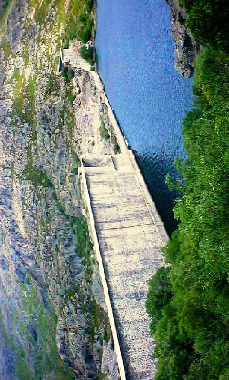
In 1954 the Malpasset Dam, a 200 feet high arch dam on the Reyran river, was completed. This dam failed in December 1956 causing 421 persons to die in floods. This was due to failure of foundation.
Vega de Tera Dam
Vega de Tera Dam
A very confident dam called Vega de Tera Dam in Spain failed in January 1959. The town Rivaldelago was fattened. Telephone poles were snapped like matchsticks. With in moments, 123 villages were drowned. Several hundred luckier ones were saved, but were rendered homeless. This time this dam was not built strong enough to bear the full weight of its intended reservoir. Heavy rains wrecked it.
Vega de Tera Dam
Vega de Tera Dam
Sometimes excessive and unanticipated earthquakes may result failure to a dam. In 1968 earthquake, the Koyna Dam in india was at the verge of failure. The engineers saved that dam by toiling hard day and neight.

Shakidor Dam Brust

The other failures are South Fork Dam due to spillway design error, Shakidor Dam due to extreme rainfall and Dale Dike reservoir, Taum Sauk pumped storage plant due to human, computer or design error.


Leading Cause of Dam Failure

a) Hydraulic failures

More than one-third of all dam failures have been attributes to these causes. These type of failure may occur due to the following reasons:

1) Overtopping

When water levels rise rapidly and without adequate warning due to flash floods, heavy rains, a landslide in the reservoir that creates a tsunami, or if a dam upstream collapses, overtopping occurs and rise in level of level of a reservoir exceeding the capacity or height of the dam. If the spillways become blocked with debris, like silt, mud or trees, or the spillway gates are not operated properly and water can not be released, there is a danger that the water level in the reservoir will rise higher than the crest of the dam and spill over resulting overtopping.

2) Erosion of Upstream Face

Wind produced waves near the top water surface and try to notch out the soil from the upstream face and may even, sometime cause the slip of upstream slope.

3) Cracking Due to Frost Action

The upper portion of dam may subject to heaving and cracking of soil due to frost action with dangerous seepage and consequent failure.

4) Erosion of Downstream Face by Gully Formation

The erosive action on downstream face of moving water from heavy rainfall, may lead to formation of gullies on the downstream face, ultimately leading to the dam failure.

b) Foundation Defects

This failure is responsible for one-third of all dam failure of whole world. The main cause of concrete dam failure is a problem with foundation. Dams built on slopes must be properly engineered to avoid issues with instability or landslides. Only the weight of a dam structures has an impact on the ground underneath. If this weight is not properly taken into account in the engineering of the dam, the ground underneath can settle unequally and compromise the foundation. Any event causing the movement of a foundation, such as earthquake, can also result failure of the dam’s foundation. High uplift pressure and uncontrolled foundation seepage can also lead the dam foundation to failure.

c) Seepage Failure

The semi-permeable dam like embankment type can be failed when too much seeps or leaks through the structure. Controlled seepage or limited uniform seepage is inevitable in all earth dams and ordinarily it does not produce any harm. Uncontrolled or concentrated seepage through the dam body or through its foundation results piping. Piping is the progressive erosion and subsequent removal of the soil grains from with in the body of the dam or the foundation of the dam. More than one-fifth of all failure of dam occur because of these reasons.

1) Piping Through Foundation

Water, through the foundation of dam, may start seeping at a huge rate when highly permeable cavities or fissures or strata of coarse sand or gravel are available in the foundation of the dam. This concentrated flow at a high gradient, may erode the soil. This leads to increase flow of water and soil, ultimately resulting in a rush of water and soil, thereby creating hollows below the foundation. The dam may sink down into hollow so formed, causing its failure.
Piping Through Foundation

2) Piping Through the Dam Body

When the concentrated flow channels get developed in the body of the dam, soil may be removed in the same manner as was explained in the foundation piping, leading to the formation of hollows in the dam body, and subsequent subsidence of the dam. These flow channels may develop due to faulty construction, insufficient compaction, cracks developed in embankment due to formation of settlement, shrinkage cracks, animal burrows etc.
Piping Through the Dam Body
4) Armed Conflict

The dams creates dangers in wars, especially in modern atomic age. The resultant failure of such a dam will create catastrophes, but also it will get contaminated by radioactivity from which there could be no escape.

This is an important point which results stress on the host of the dam. In World War II, British Royal Air Force Dambusters operate raid on Germany, in which three German dams were selected to breached in order to have an impact on German infrastructure and manufacturing and power capabilities deriving from Ruhr and Eder River.

To protect possible destruction on the civilian population and the environment, the rules of International Humanitarian Law ( IHL) are made and dams are defined as object not to be attacked. During armed conflict, dam is to be considered as an “ installation containing dangerous forces”. A protective sign consisting of three bright orange circles placed on the same axis is provided to facilitate the identification.

5) Other Reasons

Dams which are improperly maintained or built with inadequate materials or unsound design can result in structural weakness that lead to catastrophic dam failure.


Dam failure

REINFORCEMENT REQUIREMENT OF PILE

The amount of reinforcement and its arrangement vary with the loading condition and installation and driving condition. The amount and arrangement of reinforcement for different types of pile are discussed below briefly.
Precast Pile

Longitudinal Reinforcement

The minimum amount of longitudinal reinforcement should be 1.5% of concrete section. At least 4 bars have to provide in a symmetrical pattern.

Lateral Tie Spacing

At each end of pile lateral tie reinforcement consisting of 6mm dia or larger have to place at a spacing not more than 75 mm center to center, or an equivalent spiral shall have to provide through a length equal to at least three times or the pitch of spiral may be increased to 300 mm.

Clear Cover

The cover of concrete over all the reinforcements including ties, should not be less than 70 mm anywhere through out the length of piles.

Cover should be measured clear from the main or longitudinal reinforcement.

Cast-in-situ Piles

- Minimum vertical reinforcement in bored cast-in-situ piles shall be four 13 mm dia bars and embedded at least half of the pile.

- Reinforcement should be assembled and and tied together and should be placed in the piles as a unit before the reinforced portion of the pile is filled with concrete.

- When hollow stem auger is used to install piles, the longitudinal steel reinforcement should be placed through ducts in the auger prior to filling the piles with concrete.

- All pile reinforcements should have a concrete cover of not less than 65 mm.

Under-reamed Bored Cast-in-Situ Piles

Longitudinal Reinforcement

- Minimum longitudinal reinforcement in stem shall be 0.4 %.

- Reinforcement is to be provided in the full length.

- Minimum 3 bars o 10 mm of diameter mild steel or 3 bars of 8 mm diameter high strength steel be used.

Transverse Reinforcement

Transverse reinforcement should be provided with bars not less than 6 mm in diameter and at a spacing not less than the stem diameter or 300 mm, whichever is less.

In case of cohesion less soil, under-reaming should not be done in both above and below ground water table.

The minimum depth of under-reaming bulb shall be either 2.75 m or below the level of stabilized moisture content, whichever is deeper.

Under-reaming Compaction Piles

Vertical reinforcement

Minimum four 12 mm dia bars should be provided, but for piles of length exceeding 5 m and diameter exceeding 375 mm, a minimum of six 12 mm dia bars shall be provided. For piles exceeding 400mm in dia, a minimum of six 12 mm dia bars shall be provided.

Transverse Reinforcement

The circular stirrups of such piles shall be provided with a minimum of 8 mm dia bars.

Factor Affecting the Durability of the Reinforced Concrete in Seawater

Disintegration of concrete and corrosion of reinforcement is the sign of deterioration of marine concrete structure. Many researchers have identified, after laboratory investigation and extensive studies on existing marine structures, a number of factors affecting the deterioration of reinforced concrete in such an aggressive environment. Some of these important parameters are stated below:

1) Aggregate Type

The properties and proportion of constituent materials of concrete have a large influence on the durability of concrete. As the aggregates occupy up to 80% by volume of concrete, the resistance surface properties of the aggregates are important parameters affecting durability of concrete. To ensure adequate durability of marine structure, the aggregates material should be dense, non shrinking and alkali resistant.

2) Cement Content

The cement content also has a marked influence on the durability of reinforced concrete. Several researchers and authorities have been given recommendation for the minimum cement content of concrete exposed to different zone of marine environment.

3) Water-Cement (W/C) Ratio

The water-cement ratio influences both the strength and durability of concrete. According to Abram’s Law, the strength of concrete at a given age and normal temperature decrease with increasing the water-cement ratio assuming full compaction of concrete have been done. Permeability of concrete to water depends mainly on the W/C ratio, which determines the size, volume and continuity of the capillary voids. It is clear that even a small increase of W/C ratio can increase the concrete permeability to a great extent. Again, permeability is the most important Characteristics determining the long-term durability of reinforced concrete exposed to seawater as it controls the diffusion of aggressive salt-ions into the concrete. ACI 318-83 requires that normal –weight concrete subjected to freezing and thawing in a moist condition should have a maximum W/C ratio of:

- 0.45 in case of curbs, gutter, guard rail or their sections and
- 0.50 for other elements.

4) Cement Type

The resistance of concrete against the action of various aggressive agencies depends to a great extent on the type and proportion of cement. Ordinary Portland and pozzolana and sulfate resisting cement are the various types mainly used in marine concrete construction. Various researchers assessed the performance of these cements individually by either exposing the mortar and concrete specimens in the seawater or in its constituent salt solution, to study their strength and durability characteristics.

5) Air Entrainment

Harden concrete containing entrained air is more uniform, has less absorption and permeability and is more resistant to the action of freezing and thawing. Normally, about 4-6% of air by volume of concrete is entrained which is dispersed throughout, the concrete in the form of minute, disconnect bubble. It has been reported that the amount of entrained air necessary for imparting the highest resistance to concrete to frost action in the seawater is in the range of 10-20% which is more then twice as large as concrete with 3-6% air entrained when exposed to plain water in similar environment. However, the amount of air entrained 10-20% reduces the compressive strength of concrete to about one-half of the strength without air entrainment.

6) Carbonation Process

The hydrated concrete has a tendency of combining with carbon dioxide, CO2 present in the atmosphere and forming carbonates, which partly neutralizes the alkaline nature of concrete. This process is known as carbonation. When carbonation depth exceeds depth of cover to the reinforcement, the salt ions find a suitable environment leading to greater corrosion.

7) Quality of Mixing Water

Sea water contains a total 3.5% salinity of which

- 78% is NaCl ( i.e. 2.7% of total salinity)
- 15% is MgCl2 and MgSO4

According to ACI 318-83 the mixing water should be potable and free from salts. Giving no specific reference to sea water, it specifies that mortar cubes made with computable mixing water shall 7 days and 28 days strength equal to at least 90% of strength of similar specimen made with potable water.


7) Influence of Crack

Reinforced concrete structure, either reinforced develop unavoidable cracks during their service life. Cracking may stem from various causes; construction cracks as a result of initial and drying shrinkage, settlement, and heat of hydration; load cracking during normal service as a result of flexure, stress reversal, torsion, shear etc. However cracks offer a path to the interior of concrete for the deactivating and corroding agents.

8) Depth of Cover to the Reinforcement

The thickness of the concrete cover to the steel is an important factor regarding rebar corrosion in an aggressive environment. It affects the time taken for the salts to penetrate to the steel, and the subsequent rate of arrival of oxygen at the steel surface as in the case of permeability. Lesser the cover, shorter the time required to deactivate the embedded steel. Also moisture content of the cover, defines permeability to surrounding salts and gases.

9) Age of Immersion

The age of immersion also referred to, as period of procuring is the time duration of concrete commencing immediately after casting up to the formal curing. In a marine environment, procuring of concrete can be done with either sea water of fresh water. The dissolved salts start reaching with the concrete affecting its rate of gain in strength when procuring is done with seawater.

10) Diffusion of Salts Under Pressure

The harmful salt ions enter to the body of concrete at various depths under hydrostatic pressure and also to the embedded steel. This result disintegration of concrete which in turn increase its permeability and provides greater accesses to the chloride ions for coming in contact with steel. But due to limited availability of oxygen, the corrosion process is often ineffective.

11) Wetting and Drying Cycles

In marine environment, the structural concrete in tidal zone undergoes alternate wetting and drying process due to tidal action.

12) Freezing and Thawing Cycle

Concrete is greatly affected freeze-thaw cycles. The change in physical state of water ( liquid-solid) inside the mass of concrete results in an increase of volume 9%. The volume change in a cyclic fashion (freeze-thaw cycle) causes disruption of concrete by dilution process.

Component Comprising Biogas System

Biogas production is most suitable for farms that handle large amount of manure as liquid, slurry, or semi-solid with little or no bedding added. To produce a cost effective system, it should be designed by an experienced animal waste digester designer. A typical biogas system consists of the following components:

A) Manure Collection
B) Anaerobic Digester
C) Effluent Storage
D) Gas Handling
E) Gas Use


All of these components are discussed briefly:

A) Manure Collection:
A manure management system is developed in livestock farms to consider environmental, sanitary and farm operational facilities which includes collection and storage of manure. This can be collected and stored as liquid, slurries, semi-solids, or solids.

a) Raw Manure
The solid content of 8-25% is excreted as raw manure. It can be diluted by various processes.

b) Liquid Manure
Such manure is diluted to a solid content of less than 5%.

c) Slurry Manure
Manure handled as slurry is diluted to a solids contents of about 5-10%.

d) Semi Solid Manure
Manure handled as a semi-solid has a solid content of 10-20%. Water is not added to such manure and it is typically stored until it is spread on local fields.

e) Solid Manure
Manure having a solids content of greater than 20% is handled as a solid by a scoop leader.

B) Anaerobic Digester
Naturally occurring anaerobic bacteria is decomposed in a digester and manure is also treated in it during the process of biogas generation. An air-tight impermeable cover is used to trap the gas for on –farm energy use.the manure handling system defines which type of digester can be used.

Different types of digester are listed below:
a) Cover Lagoon Digester

It is used to treat and produce biogas from liquid manure( solids <>b) Complete Mix Digester

It is used to treat slurry manure with a solid content of 3-10%.
Component Comprising Biogas System

c) Plug Flow Digester

It can treat scraped dairy manure having a solid concentration of 11-13%.

d) Fixed Film Digester
It is best suited for dilute waste streams typically associated with flush manure handling.

C) Effluent Storage

The anaerobic digestion of manure produces biogas and effluent. The effluent is a organic solution having a quality to be used as fertilizer and other potential uses.
The size of storage facility and storage period depends on farm requirements during non-growing season. The longer storage facility provides flexible management of the waste to account for weather changes, equipment availability or break down or other operational management.

D) Gas Handling

The expected biogas is received from the digester and transport to the final use i.e., an engine or a plant through as a gas or a plant through a gas handling system which includes: piping, gas pump or blower, gas meter, pressure regulator, and condensate drain.

The trapped gas under an air-tight cover over the digester, is collected by pulling a slight vacuum on the collection pipe using a gas pump or blower to the end of pipe. A gas meter is provided to monitor gas flow rate. Sometimes a gas scrubber is used to purify the gas to remove corrosive compounds ( e.g., hydrogen sulfide). When warm gas is cooled during traveling through pipe system and water vapor in the gas condenses. The condensate product is removed using a condensate drain(s).

E) Gas Use

Methane content in biogas is about 60-80% which have a heating value of approximately 600-800 Btu/ft3. Such gas can generate electricity, can be used as fuel for a boiler, space heater, or refrigeration equipment, or it may be directly combusted as a cooking and lighting fuel.

Checklist for Supplies and Equipment for Earthquake

Earthquake can happen at any time, anywhere. When a earthquake hits, one have only few seconds between realization that this is an earthquake and the time when the shaking stops. This is the time; advanced planning becomes effective to make one or one’s family safer. If one knows what to expect , what to do and what supplies and equipments required to survive during quake after quake, he can make right decision and right action that may mean the difference between injury, life or death.

The necessary supplies are as below:

Ø Working gloves
Ø Ax/ maul ( minimum 6 lb)
Ø Shovel ( flat head and pointed)
Ø Broom
Checklist for Supplies and Equipment for EarthquakeØ Hammer and nail
Ø Screwdrivers
Ø Crowbar and claw tool (36” or longer)
Ø Plastic sheeting roll (4mm,10’x25’)
Ø Plastic garbage bags (heavy duty, 30 gal. or larger)
Ø Small or larger plastic bags
Ø Coil of rope 1/4”,1/2”,3/4” (25’-50’)
Ø Coil of wire
Ø Tent (family or tube type)
Ø Tarp (PVC or canvas, minimum two, 8’x10’)
Ø Sleeping bags, blanket or space blanket
Ø Cheese cloth ( to strain particles from water)
Ø Cash money (small denominations and coins )
Ø Dry food
Ø Clothing
Ø Walking shoes and shocks
Ø Local road map
Ø Fire extinguisher ( preferably a dry chemical type with a minimum size with an earthquake restraining strap, a hose-type nozzle and a metal head.
Ø Compass
Ø Flash light w/batteries or chemical light sticks, matches ( in water proof container)
Ø Small radio (battery-powered portable)
Ø Entertainment pack –family photos, note books, literature and genes

Sanitation Supplies


Ø Plastic bags ( heavy-duty garbage can size and small zipper types)
Ø Powdered chlorine lime ( proper storage is required, it is an oxidizer and is corrosive )
Ø Portable camp toilet with chemical
Ø Toilet paper
Ø Handi-wipes, wet-n-drys etc. for water-free cleanup
Ø Toilet supplies (toiletries, shampoo, toothpaste, deodorant, sanitary napkins etc.)
Ø Insect, fly, mosquito and ant sprays.


Storage Location


When organizing supplies for an earthquake, remember that you need to get to them after an earthquake has turned your house into a mess. Store supplies in an easy-to-find location that has a minimal chance of being buried under falling objects. If you are short on space, a large trash can makes an excellent storage container. If live in an apartment, the can be hidden under decorative tablecloth. Food supplies should be rotated within at least six month.

Mechanism involved drifting of continents

Diastrophism
Various stresses operating within the body of the earth result in regional crustal deformations or movements are known as diastrophic movements. This phenomenon is known as diastrophism.
Isostasy
Isostasy is used to explain various movements in the crust. The principle of isostasy is that the different masses of the earth’s crust are standing in equilibrium, tending to reach and maintain a hydrostatic balance. At certain depth these crustal blocks exert equal pressure
and stand equilibrium.

Holme’s Hypothesis of Convection Current:
Holme’s believed that neither tidal friction nor any force from outside can drift the continents and are related to mountain building. He explained the whole process with the help of convection current cycle which is operating within the earth.
Assumption
>
This convection current theory assumes the formation of convection currents within the substratum which travel from the hotter parts near the core towards cooler parts under the crust.


Formation of Oceanic Deeps


When two ascending currents diverge under a continental block, they exert a tensional force. As the convective system gain strength the tensional force also increases, resulting in rupturing and splitting of the continental blocks leaving a gap in between. The broken fragments left in between sink into gap, reaching the ocean floor.


Drifting Continents

The currents flowing horizontally beneath the continental blocks drift them. The underlying basaltic layer which provides obstruction to the continental drift, move down into the substratum under the dragging effect of the currents directed downwards.


Mountain Building


When two currents coming from opposite sides meet and are directed downwards, there is deepening and narrowing effect. The continental mass, dragged downwards and compressed, gives rise to mountains and their and their roots. The underlying basaltic layer which also gets pushed downwards undergoes metamorphism, changing into a highly compressed type of rock called Eclogite.


Restoring the Basaltic Layer

The heavy matter (Eclogite) will descend further, merging with the substratum and further on heating, changing into magma which being a lighter material will again tend to move upwards. Most of this magma or basaltic material will rise up along with ascending currents, reaching the gaps left between the torn outstretched continents, restoring the basaltic layer, also forming the basaltic plateaus and causing volcanic activity. The basaltic layer in front of the continental mass when dragged down-wards, results in the formation of oceanic deeps.


Termination of system


The convective system as explained above, results in complete circulation of the basaltic matter beneath the crust. When the convection currents begin to wane out, the system loses its power. As a result the dragging and drifting action also diminishes and finally ceases. The lighter mountain roots which were being pulled downward continuously are left to rise up.


Holme’s Hypothesis and Isostasy


This convection current hypothesis provides appropriate explanation for the continental drift and the associated and related phenomenon of mountain building. Holme’s established this system depending on Isostasy which explains very successfully


Ø The circulation and recycling of basaltic materials


Ø Formation of ocean deep


Ø Presence of sima ( viscous substratum) sometimes with patches of sial at the ocean floors.


Ø Mountain building


Ø The lighter material of the mountains and their roots.

Improved Design Strategies of Soft Storey

Reinforced concrete (RC) frame buildings are very common in the world. In such types of structure for functional requirements of parking space under the buildings no masonry in fill are provided resulting a construction with stilts.


Design Approaches

Open ground storey building is inherently poor systems with sudden drop in stiffness and strength in the ground storey. In the current design practice, stiff masonry walls are neglected and only bare frames are considered in design calculations. Thus, the inverted pendulum effect is not captured in design.

Safeguard Against Failure


The failure can be avoided following two considerations in structural proportioning:

a) To avoid soft storey

b) When soft storey cannot be avoided, providing special design provision in designing such structure.


How to Avoid Soft Storey


Architects and structural designers can use the following conceptual design strategies to avoid undesirable performance of open ground storey buildings in earthquake:

Ø Provide some shear walls at the open ground story level : this should be possible even when the open ground story is being provided to offer car parking

Ø Select an alternative structural system (e.g., RC shear walls) to provide earthquake resistance: when the number of panels in the ground storey level that can be filled with masonry walls is insufficient to offer adequate lateral stiffness and resistance in the ground storey level, a ductile frame in not an adequate choice. In such cases an alternative system, like a RC shear wall, is required to provide earthquake resistance.Some remedial measures to counter the bad performance are shown in fig:


Special Design Provision


To safeguard the soft first storey from damage and collapse code provides two alternative design approaches:

1) The dynamic analysis of the building is to be carried out which should include the strength and stiffness effects of infills as well as the inelastic deformations under the design earthquake force disregarding the reduction factor R.

2) The building is analyzed as a bare frame neglecting the effect of infills and, the dynamic forces so determined in columns and beams of the soft (stilt) storey are to be designed for 2.5 times the storey shear and moments: or the shear walls are introduced in the stilt storey in both directions of the building which should be designed for 1.5 times the calculated storey shear forces.

Economic Section

Normal beam and column sections used in construction are rectangular or circular in reinforced concrete frames. But, it is noticed that the fibers near the neutral axis are understressed compared with those at top or bottom i.e., extreme end of section from neutral axis. The fact that a large portion of the cross section is thus understressed making it an inefficient for resisting flexure.
The flexure stress is derived by

α = (MC) / I

Where, I = moment of inertia of the desire section about a reference axis (neutral axis)

C = distance from the neutral axis to remotest fibers

M = resisting bending moment


α = flexural stress at remotest fiber.


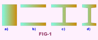
Economic SectionIf the area of a beam of rectangular section [fig-1(a)] is arranged so as to keep the same overall depth but have the shape shown in [fig-1(b)], the moment of inertia would be greatly increased, resulting in a greater moment resisting capacity. Actually, the increase in resisting moment is due to more fibers being located at a greater distance from the neutral axis. These fibers carry a greater stress and have a larger moment arm about the neutral axis to resist the applied bending moment. But, the section in [fig-1(b)] is not practical; the two parts of it would collapse together. It is necessary to use some of the area to fix these parts in place relative to each other, [fig-1(c)]. The web area transmits practically all the vertical shear.

[fig-1(c)] represents a wide-flange beam (referred to as a W shape). This is one of the most efficient structural shapes manufactured because it not only provides great flexural strength with minimum weight of material but is highly when used as a column. Another structural shape is the I beam (referred to as an S shape) in [fig-1(d)], it preceded the wide flange and because it is not so efficient has been largely replaced by the wide-flange beam.

Structural section should be such that resisting moment Mr = (αI)/c = αS must be equal to or greater the applied bending moment M.

That is

S ≥ M/ α

Where, S = section modulus of the selected section

The above equation indicates that a beam must be selected whose section modulus is equal to or greater than the ratio of bending moment to allowable stress.

The compression flanges of beams tend to buckle horizontally side sway if the beam is too long. This buckling is a column effect. When this lateral deflection is prevented by the floor system or by bracing the compression flanges at proper intervals, the full allowable stresses may be used. Otherwise, the stresses should be reduced.

Simulation of Tsunami

Physical Process


Tsunamis generate through quite distant but three overlapping physical process:

i) Generation by any force that disturbs the water column.

ii) Propagation from deeper water near the source to shallow coastal areas.

iii) Finally, inundation of dry land and consequent destruction over coastal areas.


Generation is the process by which a seafloor disturbance reshapes the sea surface into a tsunami. The disturbance may be a movement along a fault.


Assumption

Modelers assume that an ocean-surface displacement is identical to that of the ocean bottom, but direct measurements of ocean-floor motion have never been available and it may not possible ever. Instead researchers use an idealized model of the quake; they assume that the crustal plates slip past one another along a simple, rectangular plane inside the earth.


Difficulties to Simulation


Even after these assumption, predicting the tsunamis initial height requires at least 10 descriptive parameters, which includes
→ The amount of slip on each side of the imaginary plane.

→ The length of crustal plate.

→ The width of crustal plate.


But, from the seismic data only


→ The orientation of the assumed fault plane

→ The quake location and depth

→ The quake magnitude

Can be interpreted.

Tsunami, Tides and Wind-Generated Waves

The terms tsunami comes from the Japanese meaning harbor (“tsu”) and waves (“nami”). Approximately 190 event of tsunami have struck coast of Japan. According to ordinary English practice an s can be added to represent it in plural form.

The Greek historian Thucydides was the first to relate tsunami to submarine quakes, but understanding the nature of tsunami remained slim until the 20th century and sometimes it merged with tides and wind generated waves. Therefore it is very important to precisely distinguish them depending on their characteristics.


Wave Length


Everyday wind waves has a wave length (from crest to crest) of about 1000m (300ft). But, the tsunami have a wavelength of about 200km and sometimes 750km 750 km in the open ocean.

Amplitude


Wind generated waves have an amplitude of about 2m (7 ft) high. But, the tsunami have only about 1m(3ft).


Sea surface slope


The generated waves produce a steep slope of sea surface as it has relatively high amplitude and much small wave length. But, the tsunami waves generate a gentle slope due to its great wave length and small amplitude. This makes tsunamis difficult to detect over deep water.


Speed of approach

Tsunami travels at a speed of 700 kilometers per hour in deep ocean and easily pace with a Boeing 747 which can not be compared with other.


Depth of Disturbance

Breezes blowing across the ocean crinkle the surface into relatively short waves and create currents restricted to a shallow layer. Strong gales can whip up waves 30 meters or higher in the open ocean, but even these do not more deep water. Tides, which sweep around the globe twice a day, do produce current that reach the ocean bottom just as tsunami do.


Cause of Occurrence

Cyclones, hurricanes are particular form of meteorological storm which is generated by deep depression, result a storm surge which can be several meters above normal tide levels. The centre of depression has low atmospheric pressure. This surge when reaches ashore, it can inundate vast areas of land. Such a storm surge inundates Burma (Myanmar) in May 2008.

The tides are generated by the gravitational pull of the Moon or Sun.

The tsunamis are produced impulsively by an undersea earthquake or, much less frequently, by Volcanic eruptions, meteorite impact or underwater landslides.


Inland Movement of Water

Tsunamis, tides or strong storm all produce waves of water that move inland, but in case of tsunami the inland movement of water is much greater and lasts for long period, giving the impression of an incredibly high tide.


Special Feature of Tsunami

When tsunami becomes nearer to coast and travel over shallow depth, the wave is compressed due to wave shoaling and its forward travel slows below 80 Kmph (50 mph). it wave length diminishes to less than 20 Km (12miles) and its amplitude grows enormously, producing a distinctly visible wave. As the wave length still remains in the order of several km (a few miles), the tsunami may take minutes to reach its full height. Open Bays and coastlines adjacent to very deep water may shape the tsunami further into a step-like wave with steep break point.

Tsunami

Definition: Tsunami is ocean waves produced by earthquake or under water land slides. The word tsunami means "harbor waves". Tsunamis are often incorrectly refferred to as tidal waves, but a tsunami is actually a series of waves.


Properties of waves

a) Speed

i) Open ocean

The waves propagate across the deep ocean at jetliner speeds. The speed is of the order of 450~600 miles per hour in open ocean.


ii) Near coast

The wave slows down to highway speeds as it enters shallow water, and it sometimes runs ashore as a tide like flood.


b) Wave Length

Tsunami would not be felt by ships. This is due to large wave length of its propagation. This length may be hundreds of miles long.


c) Amplitude

i) Open ocean

The amplitude of waves in open ocean is only few feet. As the length of waves is large a sea surface slope of gentle value occurs.

ii) Near coast

As the waves approach the coast, their speed decrease and their amplitude increase. These unusual wave heights have been known to be over 100feet height.

Plan for Tsunami

Development of tsunami disaster plan is very important. As people do not respond appropriately, after warning is sounded, the most reliable warning becomes ineffective. Tsunami specific planning should include the following:


1) Contact with local disaster and emergency management office and learn about tsunami risk in your community. Know height of your street, hone or the place you may frequently visit as well as distance of these from the coast or other high risk waters as evacuation orders may be based on these parameters.


2) If you are not in your community and visiting an area having risk from tsunamis, contact with the hotel, motel or campground operators for tsunami warning and evacuation information and how one would be warned. Designated escape routes should be known before a warning is issued.


3) Plan an evacuation route from the place where you may present during tsunami risk. If possible, select an area 100ft above sea level or go up to two miles inland, away from the coastline. If such place is not available, go as high as you can. As every foot upwards or inland make you safer. The safe location should be such that within 15 minutes you can reach their on foot. Be prepared to further evacuation by foot if necessary as after a disaster, roads may become impassable or blocked.

4) Follow footpaths as it normally lead to uphill and inland. But many roads may parallel to coastlines. Local emergency management officials can also advice you to learn best route to take safe shelter.

5) Practicing the evacuation routes, may familiar you with the routes and can help saving your life. Be able to follow the route at night and during stormy and very cold weather. These help you to take a response quickly without requiring less thinking during actual emergency situation.

6) Listen weather report which will warn you of potential danger.

7) Talk to insurance agent. Homeowners’ policies do not cover flooding from a tsunami. Ask about National Flood Insurance Program.

8) Review flood safety and preparedness measures with your family. Tsunami is nothing but a large amount of water that crush onto the coastline, creating floods.

9) Discuss with your family what to do when all family members are not together. These will help reducing fear and anxiety during actual situation.

Protection for properties

Protection for properties can be made by taking following steps:


a) Avoid building or living in building within several hundred feet of the coastline. These areas are more likely to suffer damage from tsunamis, strong winds, or coastal storms.


b) Make a list of items to bring inside in the event of a tsunami. This list help you remember anything missing that can be swept away by tsunami waters.

c) Most tsunami waves are less than 10 feet. So elevating house will help reduce damage to your property from most tsunamis.

d) Consult with a professional for advice to derive waves away from your property.


e) Take help from engineers to check your home and make it more resistant to tsunami water. Improperly built walls may make situation worse.

Followers