
Foundation, Concrete and Earthquake Engineering

How does Diesel Hammer Work in Pile Foundation Operation?

Precast piles are driven with the help of pile driver/hammer to reach expected foundation depth. Different types of hammers are used in pile foundation construction. We have already learned about all types of pile hammer, briefly, in our previous post. Here we will discuss about diesel hammer.


The hammers used, now-a-days, have large engine of two-stroke facility. A cylindrical apparatus connects to top of pile. The weight that drives the pile, with ignition energy, consists of this apparatus and piston. As we go through the topics we will learn about the apparatus gradually.


Runbang DH50 diesel hammer
At first the weight is raised with auxiliary means, which may be a crane or any other means. Usually a crane holds this pile driver. While raising the weight air entered in to cylinder by suction.


The weight is released quickly to drop over pile. This quick release results compression of air trapped during raising. This compression raises the temperature of air to reach ignition point of fuel.


Obviously the fuel is diesel. There have facility to inject diesel fuel to such heated air. The ignition of mixture (air and fuel) generates energy which is then transferred to pile head enhancing the driving energy.


The ignition energy not only transferred to pile head but it drives the weight to its previous falling height. So the auxiliary means to raise the weight back its position is not required after initial application. While rising, the cylinder again draws fresh air and cycle stated above kept running.
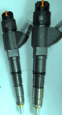

Diesel injector These cycles can be stopped willingly by pile operator or automatically when fuel injection is stopped due to run out of it. So far we have discussed about operating principle of diesel hammer. Now we will discuss about some details of apparatus and mechanism as well.

The hammer operation starts with raising piston called ram to a designated point while the raising system automatically releases ram. The ram falls by gravity over the pile top. There have mechanism with the ram and fuel ignition system.


When ram falls, this mechanism automatically gives live to fuel pump. This pump has facilities to insert fuel to such amount to result ignition successfully with optimum efficiency.


While piston falls, it closes the exhaust system through which the system draws fresh air into it. This results an entrapped condition of air. In the impact block the fuel pump releases fuel into ball pan.


Driving of pile with diesel hammer
The fuel discharged into the impact block is metered such that it provides specific amount of force to pile and at a time rebound the piston to this automatically release point of raised position.

As discussed above, while piston falls, it blocks exhaust system to entrap air. This entrapped air is compressed by the weight of piston. The compressed air produces a preloaded force of around 44,000 lbs.


The preloaded force holds firmly the impact block against pile through driving cap. While the piston exerts force the pile becomes mobilized from it position overcoming inertia and skin friction. Now our aim is to exert extra pressure by the explosion of fuel in the diesel engine.


Working principle of diesel pile hammer
From the previous topics of relative efficiency we have learned that the blow interval develops inertia and friction resistance which have to overcome by next blow and after overcoming the pile get mobilized. Here we have advantage of initial mobilization of pile by preload force and when fuel energy results pressure, pile moves without overcoming this resistance. Obviously in the next blow this resistance is again developed.


When piston strikes impact block, atomizing fuel pump and exerts downward movement to pile due to impact. The compressed air at ignition temperature of fuel results explosion which exerts greater force than that of impact and generates further downward energy to already moving pile.

The pile results rebounds on the piston and it moves towards upward. While moving up back, the exhaust system which was previously blocked in compression stroke is released. Thus the gases and explosion force is released to atmosphere. This system again draws air to its cylinder and when energy of upward movement is diminished, the piston falls again and the cycles are continued.

Why is Grouting Applied in Stabilizing Foundation Soil?

In various cases both from economy and practicability; where deep foundation cannot be adopted and as well excavation of entire problem soil or soft soil deposit is not possible, we, foundation engineers, look for stabilization of soil in improving its engineering properties.


We have discussed earlier that there have many stabilization options like, cement stabilization, lime stabilization, bituminous stabilization, chemical stabilization and mechanical stabilization. Stabilization with grouting is another method of stabilization in foundation engineering. We have discussed a related term jet grouting and other grouting methods by injection to renovate slab-on-grade foundation and regaining its previous serviceability conditions.
Dam repairing with pressure grouting
Here in this post we will discuss about suitability of grouting stabilization method.

As discussed above, this process is done by injecting a stabilizer in pressure through the soil. The soil suitable for this stabilization is high permeable soil as the stabilizers are generally of high viscosity and injection pressure makes them reach this grout to the further end of pores.


Raising effort of pavement slab sunk at junction with Polyurethane Foam Injection
As clay soils have low permeability, naturally this method is not suitable for cohesive soils of less permeability. The stabilization method we discussed in previous posts, use more or less direct blending. But this method involves injection with pressure and grout viscosity and injection pressure are the design criteria to avoid grout loss. We have discussed about grout loss in our previous post. You can read this for more information.


So this method is costlier than other stabilization methods. This method does not disturb the soil below much or almost zero. The projects where disturbance of soil to be stabilized, is not acceptable, this method is most suitable. Normal application is stabilization of soil enclosed by existing building like slab-on-grade. In stabilization of dam, that have underneath pervious stratum such method is suitable.

What are Filter Criteria for Basic Performance of Geotextiles in Soil Improvement?

Geotextiles are extensively using in many civil engineering projects where soil improvement or slope stability is of great importance. In 1958, geotextiles were first applied as filters when traditional filters of designed graded coarse grained soil were replaced by it. Now-a-days geotextiles are using in many slope stabilization and erosion recovery problems.


As a filter, geotextiles should be properly designed to ensure adequate or designed retention of erodible materials to be retained and provide sufficient discharge capacity throughout designed life of structures. Now we will learn basic filter criteria that are considered in selecting geo-textile for filter purposes. These criteria are:


Providing geotextile in stabilizing of soil slope
a. Retention requirement which considers the prevention requirements of migration of particles to be retained through geotextile.

b. Permeability requirement which ensures flow a liquid through the geotextile. Generally it is expected to establish a free flow condition. Our aim is to retain soil particles but provide a free passing out of liquid i.e. water in common cases.

c. Clogging prevention requirement, this requirement includes the performance of geotextile regarding above two criteria remain satisfactory throughout life cycle of structure i.e. the geotextile performs well with satisfying retention and permeability requirements.


But above three criteria of geotextile can be satisfied only by controlling distribution of pore sizes throughout the geotextile and largest openings of pore. Dear reader in united states the term AOS or O95 are used regarding geotextile opening size. AOS stand for apparent opening size. We will learn about AOS and O95 in our next post.

Foundation Problem with Organic Soil

Organic soil is a problematic soil. The soil that have properties that may result to serious foundation problems, where there have large uncertainly of its behavior and difficulties in sampling is exist, these are problematic soil.


So we have learned about problematic soil with above definition. Now we will learn about mineral content and origin of organic soils. Organic soils are enriched with organic contents which are generally formed due to decomposition of organic materials. In many cases, these soils may exist below other soil mass. Generally they are found in marshy place and at top soil. We will discuss about the classification of organic soil in our upcoming posts.


Fibrous organic soil
Now we will discuss about the problems with organic soils, especially foundation problems. We know that any organic materials have a characteristic of decomposition. In contact with air they become oxidized and results a destruction of slow rate. Thus the volume of organic matters is reduced resulting a compressibility property.


They may shrink excessively with compaction. Though oxidation is stated above but anaerobic reaction may be happened in most case they are main reaction. These soils have large moisture content but this is not observed in their plasticity. Organic soils, in some cases, are also corrosive.


So this highly compressible soil shows subsidence in slow rate that may produce many foundation problems. Foundation settlement, cracking in structural joints and members, sometimes corrosion in foundations, and as usual damaging utility system buried or in ground surface, are common problem with these soil. In the next post we will discuss about identifications, difficulties in sampling and testing, and classification of organic soil based on different parameters.

Different types of pile hammer for pile foundation

Pile is a deep foundation system to accommodate access structural load to the relatively firm stratum through end bearing or skin resistance and sometimes with the combination of both. We usually choose this type of foundation when loose soil deposits serving low bearing capacity for shallow foundation, or sometime problematic soil like expansive soil, collapsible soil, and also organic soil are present. Though in case of expansive soil the pile in many cases, are designed for anchorage purposes.

The names we familiar with are:

a. Drop hammer 
b. Single-acting steam hammer 

c. Double acting steam hammer 

d. Diesel hammer 

e. Vibrating hammer
Drop pile hammer for pile foundation

Single-acting steam pile hammer pile foundation operation At first, we will discuss drop hammer. In general, we are familiar with driving pile with blow; the exception is vibrating hammer. The driving operation with a hammer providing blows to piles is called pile driving operation and the equipment is termed as pile driver. We may need to drive pile both vertical and inclined direction. Normally guides are used to align the pile driving.

When a hammer is lifted to desire elevation with a rope and let to provide blow on the top of pile by free fall, the hammer is called drop hammer.

When a hammer is lifted with the help of steam pressure and let to provide blow by gravity fall; the hammer is termed as single-acting steam hammer. Hammer using steam energy, like previous hammer; have also another verity known as double acting steam hammer.

When steam energy is used to lift hammer and as well steam pressure is used to enhance downward energy, the hammer is called double acting steam hammer. From the name we can realize why this is double acting steam hammer.

Diesel hammer is lighter than double-acting steam hammer and can easily be transported. It is also operated at slow rate then double acting steam hammer. Diesel hammer is a unit which containing a fuel tank and essentially injectors.

Double-acting steam pile hammer pile foundation operation
Diesel hammer have a very large diesel engine. Obviously modern hammers are two-stroke engine. The weight consists of piston and the cylindrical arrangement that is placed on pile top.

The manufacturer of hammer specifies the rate of energy to be exerted by this pile hammer.Let consider Vulcan(016) pile hammer, which specifies the energy of 48750 ft-lb. sometimes in case of large diameter piling work more energy is required. The example is offshore drilling platform where large energy of driving is required and a capacity of 180,000 ft-lb has been rated by some manufacturers.

Vibratory pile Hammer for pile foundation operation
Now we will discuss about a pile driver that has less energy loss than our conventional hammer. This is vibratory driver. This driving technology is extensively used by Russian piling engineers. The arrangement, called oscillator, is mounted by crane or other means on the top of pile to be driven. The oscillator has pair of eccentric masses which is driven by electric or hydraulic motor. Such operation of oscillator is called vibratory driving.

Volumetric Batching and Possible Error in Concrete Proportioning

We have already learned that volumetric batching is not frequently used in concrete industry because of its incorrect measuring of ingredients of concrete mix. With this problem, in Indian subcontinent this method of batching is used even in important projects. Due to improper batching it is often allowed in small or less important construction project. Now we will learn the evil of such batching method.


If the granular portions of concrete mix are measured by volume, the resulting concrete may have different properties for a same ratio of batching when other conditions are considered same (placing handling, compaction, finishing etc). This is due to measuring error of materials, as same volume of granular part may have different weight depending on water content and voids in particles.


gauge box for volumetric mixing of concrete Consider two same volume of sand, one in moist condition and other in dry condition. A certain volume of dry compacted sand has much weight than same volume of moist loose sand. So when we measure one cubic meter of granular materials, we actually measure an indefinite quantity. For this reason concrete batching on the basis of weight is the only method for accurate proportion of a mix.


In the previous post we have learned about way of measuring cement. So we are not discussing this term here. There has no problem with water. Water can be measured by kg or liters as 1 kg of water have volume of 1 liter. Water measured in term of water/ cement ratio. Definitely the measuring criterion of cement is its weight.


But when volumetric batching cannot be avoided, we will use certain techniques to minimize errors and taking assumption. Here gauge boxes are introduced having different designed volume depending on volume of cement per bag. Dear reader we will discuss this elaborately in the next post.

Influence of Aggregate Shape on Water-Cement Ratio of Concrete

Water requirement for concrete to be compacted fully for given effort or practical effort is a measure of workability; also placing without segregation and efficient finishing are also important in workability of concrete. A workable concrete is desirable in concrete engineering to facilitate placing, compaction and other subsequent operations.


Water required for particular mix design is measured by the weight of cement as a ratio of it. Now we will learn about the influence of aggregate shape over workability of concrete. We concrete engineers are familiar with aggregate shapes of 


Crushed Stone as Coarse Aggregate
-round

-Angular

-elongated

-flaky etc.


Now we have to consider which shape has more surface area and posses more voids which are very important in measuring water requirement. Actually, angular, flaky and elongated shaped aggregate produce a concrete of harsh property while round or cubical shaped aggregate results a concrete of smooth, less frictional resistant i.e. can be compacted easily with a less compaction effort.


Later three types of aggregate have more surface area and more voids as well which leads to more placement and compaction difficulties. These types of aggregate require huge water to have only optimum compaction which leads to selection of large water-cement ratio. We have discussed about relation between strength and W/C ratio of concrete.


Crushed coarse sand
In case of round shape aggregate, comparatively less volume of water produce concrete of more workability. Dear reader you perhaps read our posts regarding high performance concrete, where one of the main aims is to reduce W/C ratio to minimum value. In many cases only 0.25 W/C is expected. Though this degree of W/C ratio cannot be achieved only by selecting right aggregate shape, but aggregate shape plays a important role over there.


The advantage of round aggregate is observed in case of river sand or gravel. This aggregate provides greater workability in comparison to aggregates that derived from crushing.

Belt Conveyors in Concrete Transportation

Dear reader we have discussed about different way of transporting/handling of concrete in delivery or placing end. Still some methods haven’t published. In this post we will discuss about belt conveyors, sometimes called concrete belt conveyors.


So far in concrete transportation system, belt conveyors are used with limitation extent considering some problems associated with this type of concrete transporting. The main objection against this system is segregation tendency of concrete which is not allowed in concrete engineering. We have discussed different aspects of segregation in our previous post; you can read these for more information.


Portable concrete conveyor system short distance
So we were on segregation. The main sources and locations of segregation tendency are:

a. Transportation on steep inclination

b. Where directional changes are provided

c. In transfer points

d. Just above the roller while belt passes over it.

e. Vibration of rubber belt is also responsible for concrete segregation


Another shortcoming of this process, not included above, are drying and consequent stiffening of concrete while it passes over long distance exposed to hostile ambient environment. When this exposure is hot, windy or dry weather, the losing of moisture takes place severely. In most cases it is required to remix concrete at delivery end before final placing and subsequent compaction work.
Concrete conveyor belt system can transport enormous amount of concrete in less accessible area.
With above bad words, you may be confused about applicability of belt conveyors. But technology is advancing rapidly to facilitate transporting concrete process and it brings some modification in conveyors system. Modern conveyors have adjustable reach, variable speed towards back and forth, travelling diverter. This system extremely useful when enormous amount of concrete has to be transferred quickly through a relatively less accessible area.


We have discussed about losing moisture; in this regard it is wise to cover the belt partially or completely depending on weather condition. Portable conveyor system is available for transporting short lift or distance. The discharge end must be designed such that the arrangement minimize segregation of concrete and ensure discharging of entire mortar form belt.

Cement Weighing and Error in Concrete Mixing

Though the title of this post is cement weighing, we will discuss about consequence of not weighing cement in concrete batching. In small concreting works, it is usual to add cement as bag considering each bag having weight 50 kg. Cement bags are considered 1.25 cubic feet and weight of 50 kg.


In actual condition this 50 kg bag, due to inherent properties of products and as well the quality and efficiency of machines, may not have exact 50 kg of cement. So an error limit has to be set for packaging of cement. In this regard, Standard of Weights and Measures (packages) Rules, 1977 provides margin of variation by 1% (this may be short or excess in quantity) for each bag.


Cement weighing hopper in concrete plant
Cement is packed in factory as 50 kg per bag; but due to error in packaging, stated above, and also during transportation and unloading and reloading operations in different places, some cement may be lost. This is prominent when jute bags are used in packing.


Now we are receiving cement bags of less weight and sometimes this may lack 5 kg or more of cement i.e. lacking more than 10% of weight and designing mix proportion according to volume batching, considering 1.25 cft obviously lead to error. This error is also observed in weigh batching when 50 kg bag is considered.


Now-a-days we are using plant-mixed concrete, with either hauling equipment or sometimes some mixing is left for agitating hauling equipments. They are well known as ready mixed concrete (RMC). We have provided numerous information about ready mixed concrete from our experience and from ASTM and ACI specifications and requirements in this blog. In RMC, weigh batching is done successfully and economically. In most cases, in Indian subcontinent, volumetric batching are used and we experienced in many cases excess consumption of valuable components of concrete. So for important and large jobs of concreting, cement should be measured accurately to have exact cement content in concrete for expected mix proportioning.

Bearing Capacity of Plastic Silt and Clay Soil

We have discussed about difficulties in piling in plastic clay, contact pressure of saturated clay, heaved piles, and numerous posts about expansive clay soil specially on black cotton soil/regur. Our posts on expansive soil become very popular. Dear reader here we will discuss about this clay soils and determination approach of bearing capacity of clay. Here we are grouped plastic silt and clay in same class as plastic silt in saturated condition act like medium clay and sometimes soft clay. So in foundation design approach they are treated as same class.


We know that primary bearing capacity of soils depends on shearing resistance of them. Being relatively fine grained the pore water pressure cannot be released easily in these types of soils and they can be assumed impermeable to some extent especially just after load is applied to the soil. Thus undrained condition prevails.


The thin walled tube samplers for clay and saturated plastic silt
So when structural loads are transferred to these soils in saturated conditions through foundation, excess pressure due to pore water is generated in fairly impermeable medium of soil mass and there have no way to dissipate these pressure quickly.


So for a short period just after loading, undrained condition leads to Φ=0 analysis. In deriving strength, undrained shearing strength is used. We know that this strength in one half of unconfined compressive strength i.e.

S=C=1/2 X qu

Considering the consolidation of such soil, the results derived on the basis of Φ=0 analysis are on safe side. Dear reader we will discuss this term elaborately in the next post. The thin walled tube samplers are successfully used to take specimens to set under laboratory testing but more accurate methods can be used depending on economy. In our sister blog “structural concrete foundation engineering” we have published a post discussing elaborate method of exploration of this soil in relation to economy.

Behavior of Concrete Microcracking Under Loading

Cracking of any form can lead to failure of concrete members. So in concrete engineering, this term is studied and handled with care. We have provided a basic idea about microcracking in the last post; here in this post we will discuss about the cracking pattern, elongation of cracking and appearing new cracks under loading. We have already learnt that this types of cracking remains in the concrete even in preloading state. Let’s learn about what happen when concrete becomes stressed to its ultimate loading.


Microcracking concrete under lightmicroscope
Microcracking in concrete under
lightmicroscope (Green llines)
Microcracking is determined by optical microscope as it is often not visible under human eyes. But a upper limit of cracking (0.1 mm) that can be detected by eyes without any visual instrument, is found in some findings. For engineering applications a lower limit of cracking can be set.


We will discuss about behavior of microcracking under cyclic loading in the next post. In this post we will discuss about gradually application of loads. The microcracks show stability under increasing load up to around 30 percent of ultimate load. Beyond this stress the cracks expanded with their number, length and width. As we discuss in the last post the cracking weaken concrete under its tensile stress.

Microcracking in concrete under uniaxial tension

The white lines are mortar cracks and black lines stand for combined cracking in concrete under uniaxial tension
Now the stress level depicted above is not fixed, it’s have sensitivity of W/C (water to cement) ratio in the paste. But in this stage cracks propagates slowly.


So far we are talking about cracking between interface of cement paste and coarse aggregates. When stress reached near ultimate capacity of concrete, cracks formed in the mortar i.e. bond between fine aggregate and cement paste are destroyed with the gradual increment. 
When load is increased to (70 to 90) percent of ultimate strength of concrete, cracks make their way through the mortar. A new pattern of cracking in concrete in continuous form is developed which release the bond between fine aggregate and cement paste.


The cracking state discussed above is fast propagation stage. As discussed in last post, reaching stable stage depends on water to cement ratio. Here, in this fast propagation cracking stage, the starting point depends on strength i.e. initiation of this stage is higher in higher strength concrete and lower in normal strength concrete.


Microcracking under uniaxial compression in unconfined state
Higher strength concrete shows better performance than normal strength concrete in both stages i.e. the number, width and length of cracks, in all respects, high strength concrete performs well. Cumulative length of cracking of such types is measured using the neutron radiography. The high strength concrete possesses lower values in cumulative length of microcracks as usual.


The commencement of fast propagation stage of cracking corresponds to discontinuity in volumetric strain. We will discuss about volumetric plotting in determining poisson’s ratio elaborately in our upcoming post. Here we are providing a basic idea about this. We all know about stress-strain graph; when volumetric strain is counted as strain and steady but rapid increasing of loading is applied, above particular stress level, poisson’s ratio shows rapid increment, due to formation of extensive vertical cracks. When stress level is increased further the volumetric strain variations changes sign; we are talking about this point.
Volumetric strain in concrete cylinder (increasing loading)
What would be under sustained loading? Under sustain load failure is matter time. Both high strength and normal strength concrete fails under this sustained loading. 

Structural Sandwich Without Earthquake Agitation, Savar Bangladesh

People are asking their engineers about earthquake safety and vulnerability of their dwelling or owned structures. But we have seen structural collapse of huge commercial building without any influence of earthquake (24th April, Rana Plaza, Savar, Bangladesh). We will discuss technical issues of this structure; not political, administrative or legal factors.


This building was used as garments factories of several owners with markets and office spaces for institutions like bank etc. Being commercial building, to have uninterrupted electricity supply, several generator were used there. BGMEA confirmed that during collapse 3122 workers were working and a total 5000 workers were employed in different floors of garments factories. The rest workers do not joined work due to panic of cracks observed 23 April, the day before collapse.


Structural collapse during Christchurch earthquake,23-2-2011
Now come to the point earthquake. The construction industry of Bangladesh is not quite good. Here workmanship of worker is low and also many owner and construction contractors are looking for cheap, low quality work for more savings. Many building of the major cities like Dhaka and Chittagong (not considering suburban or rural areas) were constructed and still constructing disobeying rules of local and government authority.


Dear audience the image above was taken from the collapse in Christchurch earthquake, which resembles somewhat to rana plaza. The difference is that there was a release of huge strain energy due to deformation of plate boundary below South Islands (Australian plate and Pacific plate). The energy released by this earthquake was 6.3 (in magnitude scale). In savar not such agitation was felt. The structure was collapsed due to service loads, unexpected vibrations and its own weight.


Structural collapse during eastern turkey earthquake (M-7.1)
The next image below was taken from Erics, Turkey; this failure seems more close to savar collapse. But this collapse was also associated with an earthquake of magnitude 7.1.


The last figure was taken from Mexico City. Here we can notice that bottom five floors were sandwiched. But this was due to one the great earthquake of the world; Magnitude 8.1 Mexico earthquake. The bottom floors had mass irregularity and sandwiched.

Structural failure during magnitude 8.1, Mexico city earthquake 19-9-1985
The structural irregularity and system limitation are published in this blog; you can visit this post for more information. We can conclude about rana plaza that there was instability in foundation, mass irregularity, inadequate confinement in joint of members (lack of ductility) poor construction materials and more prominently the lust of owner to be richer.
Total Structural collapse of Rana Plaza-all floors are sandwiched
Now we are sharing some images of rana plaza collapse below. The structural weakness of this death trap will be discussed in our next post. Till then good bye.

Followers