
Foundation, Concrete and Earthquake Engineering

Quality of water in concrete Mix

Introduction

Concrete is a chemically combined mass which is manufactured from binding materials and inert materials with water. It is most popular construction material due to its unique durability and reasonable strength; more interestingly can be modified and designed for wide range of strength requirements and set under variable environmental conditions. Cement is the most important material of concrete which is produced at the cost of environmental emission of CO2; to produce 1 tonne cement nearly 900 kg CO2 is released in the environment. So such an energy intensive materials constitutes concrete which may be seriously affected by (both strength and durability point of view) by relatively available and cheap but essential element water; more precisely impurities in water. Quality of mixing water are mainly considered for performance of concrete in both fresh and harden state.

Impurities in mixing water intervene the setting time of the paste and may produce detrimental effect on strength and durability of concrete also. When impurities are chemically active, they may take part in the chemical reaction contributing significant change in setting, hardening and development of strength of concrete. More over health hazard during handling these water should carefully considered. In this regard past performance of a particular source of water can be used to evaluate suitability of water; if not available, some testing inevitable to evaluate water for setting time, compressive strength and durability.


Function of Water in Concrete

Three water serves the following purpose:
  1. To wet the surface of aggregates to develop adhesion because the cement pastes adheres quickly and satisfactory to the wet surface of the aggregates than to a dry surface.
  2. To prepare a plastic mixture of the various ingredients and to impart workability to concrete to facilitate placing in the desired position and
  3. Water is also needed for the hydration of the cementing materials to set and harden during the period of curing.
The quantity of water in the mix plays a vital role on the strength of the concrete. Some water which have adverse effect on hardened concrete. Sometimes may not be harmless or even beneficial during mixing. So clear distinction should be made between the effect on hardened concrete and the quality of mixing water.

Potable water as mixing water


The common specifications regarding quality of mixing water is water should be fit for drinking. Such water should have inorganic solid less than 1000 ppm. This content lead to a solid quantity 0.05% of mass of cement when w/c ratio is provided 0.5 resulting small effect on strength.

But some water which are not potable may be used in making concrete with any significant effect. Dark color or bad smell water may be used if they do not posses deleterious substances. PH of water to even 9 is allowed if it not tastes brackish. In coastal areas where local water is saline and have no alternate sources, the chloride concentration up to 1000 ppm is even allowed for drinking. But this excessive amount of alkali carbonates and bicarbonates, in some natural mineral water, may cause alkali-silica reaction.

Acceptable source of water


Besides potable water, various new and existing sources are available for mixing water which can be used for complete and partial replacement of valuable potable water. This includes

• Ground water

• Reclaimed water

• Treated water from municipal sewer

• Waste water of ready-mix concrete plant etc.

In many regions of the world there have scarcity of water like Dubai and Qatar and the local authorities are looking for new sources and reused water. There treated water are used for agricultural requirements and daily needs for construction industry. like washing aggregates, as concrete mixing water and curing of the same. Water from river and sometimes even sea are considered suitable if it is free from brackish matter. In arid regions, brackish groundwater is mixed with desalinated water and considered suitable for concrete production and for concrete slurry too.

Sampling guideline for mixing water


In addition to testing on constituent of concrete like aggregate cementitious materials and admixtures etc., testing of water is an important part of quality control of concrete. A systematic testing schedule for water testing yields higher efficiency of concrete and assure good performance in regard of strength and durability.

Important thing to remember is that water can be changed by chemical, physical or biological reactions; such modification may occur during sampling and at the time of analyzing. So it should be tested before using in concrete.

Collection of sample


The location of sampling should be at mid-stream and extracted from mid depth, as far as possible. When there have obstructions or major discharges are fall into river, the sample should be taken in downstream of discharges by a distance more than 100m in case of small stream; in a word, the site should be such that no change in water in the stream are seen with naked eyes. In case of wide river at least three samples should be taken along the cross section.

Sampling of waste water


When water from narrow effluent channels of treated sewers are to be tested, the sample should be taken from one third depth of water neither skimming the top surface nor scrapping the bottom. It is important to locate site having sufficient flow so that no nearby deposition is occurred. Caution should be taken during sampling to keep in-situ condition of dissolved gas i.e. must not be agitated to liberate dissolved gasses or to cause some degree if aeration.

It was observed that sewage flows are often intermittent which requires to collect samples an hour interval throughout 24 hours. At room temperature waste water generally decompose rapidly, so test set-up for certain parameter should be available at site. These are as follows:

  • Dissolved oxygen
  • Residual chlorine
  • Sulfides
  • PH
  • Nitrites etc.
For some tests addition of preservatives just after collection of water will be enough.


Can ready-mix concrete washout water be used in water?


It is recommended in AS 1379 and ASTM C94, that water used in washout operation in ready-mix concrete plant can be used in concrete as mixing water. 
Only requirement is to store it in such a way that contamination from deleterious matters is prevented and water is collected from storage outlet. Water should conform ASTM C 1602; the sources and testing frequencies and other requirements of testing to qualify water sources. According to ASTM C94 water may be water itself or may be ice or any forms of moisture on the aggregate surface and wash water remains in the drum of truck mixer can be used for concreting next batch.


Plant washout water often called recycled ready-mix water. In 2007 experiment results were published by GL Low et al. about the requirements of recycling of cement-slurry water found from ready-mix concrete batching plant. He also examined the performance of concrete casted from reused water without any treatment. This study revealed the effects of application of such water in concrete mix on both fresh and hardened concrete based on the requirements of ASTM C94 and BS4550. The interesting thing was that they used two criteria namely specific gravity and PH; slurry water from such source can meet acceptance criteria based on concrete performance in setting time, compressive strength and drying shrinkage, when specific gravity of recycles water not exceed 1.03 and PH value of water lies between 12.3 to 13.3.

Determination of Suitability of Mixing Water


A simple way of determining the suitability of such water is to compare the setting time of cement and the strength of mortar cubes using the water in question with the corresponding results obtained using known suitable or distilled water. About 10% tolerance is generally allowed. Such tests are recommended when water for which no service record is available containing dissolved solids in excess of 2000 ppm or, in excess of 1000 ppm. When unusual solids are present a test is also advisable.


Quality Parameters
Maimum Limit (ppm)
Chlorides
500
SO3
1000
Alkali Carbonates
and Bicarbonates
1000
Turbidity
2000

The effect on concreting for different types of contamination or impurities are described below:

Suspended Solids

Mixing water which high content of suspended solids should be allowed to stand in a setting basing before use as it is undesirable to introduce large quantities of clay and slit into the concrete.

Acidity and Alkalinity

Natural water that are slightly acidic are harmless, but presence of humic or other organic acids may result adverse affect over the hardening of concrete. Water which are highly alkaline should also be tested.

Algae

The presence of algae in mixing water causes air entrainments with a consequent loss of strength. The green or brown slime forming algae should be regarded with suspicion and such water should be tested carefully.

Sea Water

Sea water contains a total salinity of about 3.5%(78% of the dissolved solids being NaCl and 15% MgCl2 and MgSO4), which produces a slightly higher early strength but a lower long-term strength. The loss of strength is usually limited to 15% and can therefore be tolerated. Sea water reduces the initial setting time of cement but do not effect final setting time.

Chloride

Water containing large amount of chlorides tends to cause persistent dampness and surface efflorescence. The presence of chlorides in concrete containing embedded steel can lead to its corrosion.

Moisture Content of Aggregate


Aggregate usually contains some surface moisture. Coarse aggregate rearly contains more than 1% of surface moisture but fine aggregate can contain in excess of 10%. This water can represent a substantial proportion of the total mixing water indicating a significant importance in the quality of the water that contributes surface moisture in aggregate.


Effect of lead exist in mixing water


An investigation was conducted on behavior of concrete under existence of heavy metal in mixing water by Madhusudana Reddy, B and et al (2011). They examined the effect of presence of lead (Pb+) in mixing water on setting times, compressive strength, soundness and attack of sodium-sulfate on high strength cement mortar. Two types of specimens of cement mortar were used, one was casted with deionised water and others were casted with deionised water with different concentrations of lead. The lead concentration used were 10, 50, 100, 500, 1000, 2000, 3000, 4000 and 5000 mg/liter. 

The results were interesting, as compared to reference specimens, it was figured out from results that specimens having high concentration of lead lost significant strength with a significant increase in setting time of cement in mortar. However, a marginal increase in setting time and compressive strength was found at a concentration of 2000 mg/liter. 


Impurities influencing setting time of concrete 


H. Y. Ghorab and et al (1990) have studied the effect of water (from natural sources) on the setting time of cement and reported that setting time of ordinary portland cement mainly dependent on quality of water. As compared to setting time of concrete cast of tap water, a reduction of 4% was observed when used water from the Nile river and approximately 25% reduction was found in concrete cast with groundwater; same result also found for sea water. 


V. V. Red and et al. studied on the setting time and development of strength in fly ash concrete under alkaline water in laboratory condition. It was found that initial and final setting time of concrete either accelerated or retarded depending on type of alkalinity rendered by sodium carbonate or sodium bi-carbonate. When sodium carbonate exists in mixing water, both initial and final setting times are accelerated when the concentration is 6 gm/liter and 4 gm/liter respectively. In case of sodium bi-carbonate, both initial and final settinh time are retarded when its concentration in mixing water is equal to 4 gm/liter and 6 gm/liter respectively. Compressive strength and tensile strength were found reduced with increase in sodium carbonate and sodium bi-carbonate content in mixing water in excess of 6 gm/liter and 10 gm/liter respectively. 

African Plate

The earth has two kinds of crust. The continents are mostly made of thick granite. When continents pull apart, the gap is filled by thin crust made of basalt. In plate tectonics, a continent is any piece of continental crust surrounded by oceanic crust or plate boundaries. Madagascar is a continent. When Africa and eastern Gondwanaland (India, Antarctica and Australia) began to pull apart about 120 million years ago, Madagascar originally moved as part of eastern Gondwanaland. It was originally attached to Kenya, and drifted south until it reached its present location. Then the crust broke on the east side of Madagascar, leaving it attached to the African Plate.
The westerly side is a divergent boundary with the North American Plate to the north and the South American Plate to the south forming the central and southern part of the Mid-Atlantic Ridge. The African plate is bounded on the northeast by the Arabian Plate, the southeast by the Indo-Australian Plate, the north by the Eurasian Plate and the Anatolian Plate, and on the south by the Antarctic Plate. All of these are divergent or spreading boundaries with the exception of the northern boundary with the Eurasian Plate (except for a short segment near the Azores, the Terceira Rift).
The African plate, shown in pinkish-orange.
Fig-2 Map of East Africa showing some of the historically active volcanoes(red triangles) and the Afar Triangle (shaded, center) -- a triple junction where three plates are pulling away from one another: the Arabian Plate, and the two parts of the African Plate (the Nubian Plate and the Somali Plate) splitting along the East African Rift Zone (USGS).

The African Plate comprises several continental blocks or cartons, stable continental blocks of old rocks, which came together to form the African continent during the assembly of the supercontinent Gondwana around 550 million years ago. These cratons are, from south to north, the Kalahari, Congo, Sahara and West African craton. Each of these cratons can further be subdivided into even smaller blocks or terranes, sutured along pre-Gondwanan orogenic belts.
The African plate, shown in pinkish-orange.
The African Plate is rifting in the eastern interior along the East African Rift. This rift zone separates the Nubian Plate to the west from the Somali Plate to the east. One hypothesis proposes the existence of a mantle plume beneath the Afar region, while an opposing hypothesis asserts that the rifting is merely a zone of maximum weakness where the African Plate is deforming as plates to its east are moving rapidly northward.


The African Plate's speed is estimated at around 2.15 centimeters per year. It has been moving over the past 100 million years or so in a general northeast direction. This is drawing it closer to the Eurasian Plate, causing subduction where oceanic crust is converging with continental crust (e.g. portions of the central and eastern Mediterranean). In the western Mediterranean, the relative motions of the Eurasian and African plates produce a combination of lateral and compressive forces, concentrated in a zone known as the Azores-Gibraltar Fault Zone. Along its northeast margin, the African Plate is bounded by the Red Sea Rift where the Arabian Plate is moving away from the African Plate.


The New England hotspot in the Atlantic Ocean has probably created a short line of mid to late-Tertiary age seamounts on the African Plate but appears to be currently inactive.

The 1960 Valdivia earthquake

The Great Chilean Earthquake is also known as 1960 Valdivia earthquake. This quake was preceded by 4 foreshocks bigger than magnitude 7.0, including a magnitude 7.9 on May 21 that caused severe damage in the Concepcion area. Many aftershocks occurred, with 5 of magnitude 7.0 or greater through Nov 1. It came after a smaller earthquake in Arauco Province at 06:02 on 21 May 1960. Telecommunications to southern Chile were cut off and President Jorge Alessandri had to cancel the traditional ceremony of the Battle of Iquique memorial holiday to oversee the emergency assistance efforts. The government was just beginning to organize help to the affected region when the second earthquake occurred at 14:55 UTC on 22 May in Valdivia.

The second earthquake affected all of Chile between Talca and Chiloé Island, more than 400,000 square kilometers (154,440.9 sq mi). Coastal villages, such as Toltén, disappeared. Later studies argued that the earthquake actually had 37 epicenters through a 1,350 km (839 mi) north-south line that lasted from 22 May to 6 June. At Corral, the main port of Valdivia, the water level rose 4 m (13 ft) before it began to recede. At 16:20 UTC, an 8 m (26 ft) wave struck the Chilean coast, mainly between Concepción and Chiloe. Ten minutes later, another wave measuring 10 m (33 ft) was reported.

The Great Chilean Earthquake or Valdivian Earthquake is the most powerful earthquake ever recorded. The quake occurred in the early afternoon (19:11 UTC) of May 22, 1960, and had a 9.5 rating[1] on the Moment magnitude scale having the epicenter near Cañete (see map) some 700 km (435 miles) south of Santiago, although Valdivia, Chile was the most affected city. The rupture zone is estimated to be about 1000 km long, from Lebu to Puerto Aisen.

On May 24, Volcan Puyehue erupted, sending ash and steam as high as 6,000 m. The eruption continued for several weeks.

Severe damage from shaking occurred in the Valdivia-Puerto Montt area. Most of the casualties and much of the damage was because of large tsunamis which caused damage along the coast of Chile from Lebu to Puerto Aisen and in many areas of the Pacific Ocean. Puerto Saavedra was completely destroyed by waves which reached heights of 11.5 m (38 ft) and carried remains of houses inland as much as 3 km (2 mi). Wave heights of 8 m (26 ft) caused much damage at Corral.

Its resulting tsunami affected southern Chile, Hawaii, Japan, the Philippines, eastern New Zealand, south east Australia and the Aleutian Islands in Alaska.Tsunamis caused 61 deaths and severe damage in Hawaii, mostly at Hilo, where the runup height reached 10.6 m (35 ft). Waves as high as 5.5 m (18 ft) struck northern Honshu about 1 day after the quake, where it destroyed more than 1600 homes and left 185 people dead or missing. Another 32 people were dead or missing in the Philippines after the tsunami hit those islands. Damage also occurred on Easter Island, in the Samoa Islands and in California. One to 1.5 m (3-5 ft) of subsidence occurred along the Chilean coast from the south end of the Arauco Peninsula to Quellon on Chiloe Island. As much of 3 m (10 ft) of uplift occurred on Isla Guafo. Many landslides occurred in the Chilean Lake District from Lago Villarica to Lago Todos los Santos.

Energy released by an Earthquake

Among the earthquake generated energy, traveled through the earth producing disruption, the only quantity that can be measured is that which is radiated through the earth. The total energy from an earthquake includes energy required to create new cracks in rock, energy dissipated as heat through friction, and energy elastically radiated through the earth. Of these, the radiated energy that shakes buildings and is recorded by seismographs.

The radiated energy can be obtained in various ways. Historically, the radiated energy was estimated empirically (from observations) from magnitude Ms through the Richter formula, log Es = 4.8 + 1.5Ms, where Es is seismic energy in Joules. In this formula, magnitude is measured first, after which the formula is used to obtain Es. With modern instrumentation, energy can be measured directly from velocity seismograms and converted to a magnitude. If Es is energy in joules, the energy magnitude Me is obtained by Me = (2/3) log Es -2.9. If Me is not available, the seismic moment Mo of an earthquake can provide an empirical estimate of radiated energy. After Mo is measured, it is converted to a moment magnitude Mw by Mw = (2/3) log Mo – 6.0 where Mo is in Newton-meters (Joules). Mw is then used as the magnitude in the Richter formula to obtain an estimate of radiated energy.

It should be noticed that Me and Mw do not necessarily have the same numerical value because they measure different physical quantities. Mw is a magnitude that is derived from low-frequency displacement spectra whereas Me is measured from higher frequency velocity spectra. Mw is a measure of the area of rupture and the average slip across the fault, whereas is Me is a measure of the shaking from an earthquake.

Magnitudes and corresponding energy (Joules and tons of TNT)


Magnitude
Es (from Me)
Es (from Ms or Mw)
Tons of TNT
Nuclear Bomb Equivalence (# of bombs)
40.22E+110.63E+1115.0.00
50.71E+120.20E+13475.0.02
60.22E+140.63E+1415023.0.79
70.71E+150.20E+16475063.25.0
80.22E+170.63E+1715022833.790.6
90.71E+180.20E+19 475063712. 25,003.3


Once the energy is known in Joules, it can be compared to the explosive energy of TNT. One ton of TNT has an energy of 4.2*10E09 Joules. In July 16, 1945 the first atomic bomb, or A-bomb, exploded on , Alamogordo, N.Mex. It produced an explosion equal to that of 19,000 short tons (17,000 metric tons) of TNT."

Critical Construction Process Requiring Good Workmanship


In reinforced concrete frame construction, it is very important to have qualified work crews with appropriate experience and competent workmanship. It is also very important to have a feasible and well-thought construction sequence to let the crews perform their tasks in a proper and timely manner. The construction crews are the last, but vital link, in the construction process.

The design engineer and the architect play important roles in ensuring that the design is feasible and can be understood by construction crews.

The design engineer should keep the structural configuration and detailing of the structural system and its sub-elements as simple and straightforward as possible. It is good practice to use standard or typical detailing as much as possible. Of course, it is the responsibility of the whole building team --from the architect and the design engineer to the field crews-- to build a good quality building.

The key processes where workmanship is critical in construction are:
1) Steelwork: the steelwork has to result in reinforcement layouts per the specifications given in the structural drawings. Reinforcing elements should be clean and
should not have any dirt or oil on them (see Figure 1).

2) Formwork: to be able to cast reinforced concrete elements properly, good quality forms need to be built. This requires use of clean, leak-proof and tightly constructed formwork systems, characterized by adequate stiffness and strength. Where necessary, proper falsework may need to be incorporated into the formwork construction to support the forms.

3) Proper placement of steelwork into the forms: reinforcing steel assemblies need to be placed and secured within the forms in such a way that the design specifications (such as minimum concrete cover thickness) have been met. This would prevent future corrosion of the reinforcement and spalling of the concrete. The steelwork should not be displaced or distorted when fresh concrete is placed into the forms.

4) Concrete work: transportation, handling, placement and consolidation of fresh concreteshould be done properly. Accumulation or loss of water, or segregation of aggregate in the concrete mix should be avoided as much as possible. If such alterations of the concrete matrix take place, the concrete mix should be reconstituted before placing the fresh concrete into forms. Fresh concrete should be poured into the forms and properly distributed (consolidated) within and around the steel reinforcing elements. Use of vibrators or other instruments that enhance consolidation of the concrete within forms is recommended. It is extremely important to have good bond

Storage of Cement

Storage of cement is a noteworthy item, because proper arrangements for storing the cement have to be made in the factories before sale or on large construction projects before use. Proper Storage preserves its quality and fitness for use. To prevent its deterioration it is necessary to protect it from rain, sun, winds and moisture.

Moisture is the first and the greatest danger to be gaurded against. Cement has great affinity for moisture and hence it should be stored well shieled from moisture laden current of air. The exposed cement is attracted by air setting which gradually spreads. It gives to the formation of lumps. If the lumps fromed are so hard that they can not be powered by passing between the fingers, it should be concluded that the cement has been rendered useless for any sound construction.

Requirement for storehouse of cement:

It is very common in construction projects, storehouses or godowns are made at site to store cement for few days. Though these storehouses are a temporary construction, they must be constructed following requirements as below:

• The walls of storehouse must be made to prevent dampness and plastered properly, 

• A proper water proofing must be applied to roof of storehouse, 

• An elevated floor of at least 300 mm above ground level must be constructed to prevent inflow of water.For economy, flooring may be constructed using two courses of bricks (150 mm thick layer of dry bricks) over a consolidated earth layer having thickness of 150 mm above a ground surface.

• For more protection cement bags are usually staked over wooden planking connected by batten. The planks are kept 100-200 mm above floor; to save timber, often concrete are used. 


• If provision for windows is kept, least number of windows having smaller size should be selected. These should be kept closed tightly to prevent moisture movement from outside of store house.

• A new storehouse is usually not used for storing cement; the exception is when structure is dried properly.

Temporary storage of cement:


It is the special case when cement is required to stored open at site for one day or two. In such situation cement bags should be staked on dry wooden platform resting on brick masonry, dry sand or may be aggregates concrete and raise 150 mm above ground surface.

This stack of cement must be covered with polythene sheet or tarpaulin completely to give protection against ambient moisture. There should have sufficient overlap of sheet on each other. But whatever the protection may be no temporary storage for cement in open condition is allowed in wet season.

Storing information:


The following information should be noted at the time of storing cement bags:

• Cement type
• Net weight of cement (approximately)
• Date of manufacture
• Manufacturer’s name or trade mark
• Certification mark of local authority.


Removal of cement from store:


While removing cement bags from storage, bags should not be removed from only one layer at the front rather two or three layer from the back should be taken off. It will produce a stepped back rows which eliminates over-turning possibility of bags.

While removing “first in, fist out” practice is followed during consumption of bags; i.e. the oldest bags are taken out first. Bags stored having separate invoice should be stacked in storehouse separately. So that one can inspect each consignment easily and can be taken out following proper sequence.

Cement should be stored in dry, leak proof and moisture proof sheds. The shed for the storage of cement should have minimum number of windows and close fitting doors. The cement bags should be stacked on wooden planks placed about 150 to 200 mm above the floor of the shed and a space of 450 to 600 mm should be kept all round between the exterior walls and the stacks.

To prevent possibilities of lumping under pressure, the maximum height of stack should not exceed 15 bags. The width of stacks should not be more than four bags or 3 m. In stacks more than 8 bags high, the cement bags should be arranged alternatively lengthwise and cross-wise so as to ensure stability of the stacks and to prevent danger of the bags in stack topping over.
In monsoon or in situations when it is necessary to store cement for unusually long periods, the cement stacks should be completely enclosed by 700 gauge polyethene sheet or some other water-proofing membrane materials.
The stack should be arranged in such a manner that cement bags can be removed on principle of first come first served i.e. oldest cement should be taken out first.

Prestressed Concrete Piles

Introduction of prestressed concrete piles has reduced the weight of precast piles providing a advantage of easy handling. The weight of very large pile is reduced by casting 200 mm to 300 mm diameter fibre tubes inside the piles at the time of concreting. In casting prestressed concrete piles, the pretensioning cables required for each piles are subjected to the required pull (tension) in the casting bed. The fibre tube for forming void in the pile (if needed) is securely held in position in side the form work and the piles reinforced with the pre-tensioned cables are concreted in a row. The casting bed can be made to accommodate 2 to 5 lines of piles 120 to 150 metre long. Prestressed piles are provided with lifting hooks at 1/5 th of the pile length from each end.

In general, square prestressed concrete piles of length 50 times the thickness can be handled with a single point pick-up and up to 60 times the thickness with two point pick-up.  Piles 500 mm square and smaller are usually cast solid, whereas pile above 500 mm square may be cast with 200 mm to 300 mm diameter cored hole(void).
Prestressed Concrete Piles On account of their reduced weight, prestressed concrete piles have definite handling advantage over precast piles and as such they are getting increasingly popular these days. When compared with reinforced concrete piles, prestressed piles have proved to be extremely durable in tidal zones and for harbour installations, where unsupported lengths of the piles becomes considerable. Their load carrying capacity is high and they are capable of resisting uplift forces and combined moments. in addition, they can withstand extremely hard driving stresses which may be far more than that which a conventional type of reinforced concrete pile can bear.
Preparation of Paints

Paints forms a thin film on drying on the painted surface which is applied in the from of liquid on timber, metal, brick or other materials. The paint film provides a protection or decoration or both to applied surface.

In most case white lead oil paint forms the basis of all the paints of light or bright colors. The base which is usually white lead is ground in linseed oil to the consistency of paste. Alternatively the base may be obtained in the form of the paste directly form the market.

The base in the state of stiff paste is then softened or " broken up'' by adding linseed oil in a small quantity at a time and then stirring the paste with wooden paddle. If a colored paint is desired the proper coloring pigment is ground very fine and mixed with linseed oil to the consistency of paste separately. Driers, if used should also be separately ground in linseed oil and the paste mixture of the three i.e. the base, the coloring pigment and the drier, is further thinned in to the consistency of cream by adding more linseed oil and stirring it well. The mixture is then strained through a fine canvas or a fine sieve. The paint is thinned to the desired consistency by the addition of oil or turpentine or both, just before it is to be used.

The paint thus prepared, should be used and consumed at the earliest. If the prepared paint has to be kept unused for some time, it should be covered with a film of water to protect it from drying or shrinking. Ready-mixed paints of varying composition and color are now produced by many manufactureres all over the world. Ready-mixed paints are generally too thick for direct application and as such they are thinned to desired consistency by adding suitable thinners and by stirring it well.

Handling of Reinforcement at Site

Whatever be the magnitude of R.C.C work, it is necessary to prepare a bar bending schedule based on the structural drawing prior to start of handling reinforcement at site. Bar bending schedule is a descriptive list containing details regarding the exact shape, dimension and diameter of each and every bar together with the number of bars of each shape.]


Bars are cut to the desired lengths and than bent cold in a accordance with the details given in bar bending schedule. Before placing the bars in position in the formwork it is necessary to ensure that the reinforcement is clean and free from loose mill scale, loose rust, oil and other coating. This precaution is necessary to meet the requirement of good bond between concrete and steel for monolithic behavior.


The reinforcement should be placed accurately in position and maintained in position by tying bars at junction with binding wire or by welding. To ensure proper cover to reinforcement, small prercast cover blocks made out of cement mortar are used. The cover blocks are inserted below the reinforcement mesh and tied to it with the help of binding wire, prior to concreting. In addition, precaution should be taken to prevent the displacement or distortion of reinforcement during concreting.

Safe Building Configuration

From the beginning of the designprocess, the earthquake resistance of a building have to considered. It is much more difficult and rarely satisfactory to achieve this afterwards. If the architect requires an asymmetric building, it can still be analysed and designed to be earthquake resistant (however this is outside the scope of this post). But, in many cases a wise re-arranging of elements of structures results a safe structures.

Avoid Structural Weaknesses in the Building Configuration

The concept design and building configuration must avoid (or take account of) structural weaknesses including asymmetry in plan and elevation. If possible the building should be symmetric.

Try to achieve:

1. Continuous load paths from roof to foundations

2. Moderate dimensions of structural members i.e. avoid very slender columns, beams and walls (minimum dimensions are given in codes, texts and guidelines).

3. Good connections between all elements, especially heavy elements

4. Robust connections between structure and foundations

5. Lightweight roof and other elements in upper portion of building

6. Transfer of horizontal loads e.g. by use of floor diaphragms

7. Good separation between adjacent buildings to prevent pounding

8. Eliminate structural weaknesses such as stairs acting as struts (which redistribute seismic loads)

9. Robust connections from main structure to dormer roofs, gables, other decorative features, parapets and chimneys.

Avoid:

a. Soft storeys, i.e. a storey, often the ground floor, which is considerably less stiff than the other floors

b. Short column effect; where stiff part height infill panels concentrate the loads in short columns

c. Stiff non-structural elements that attract loads - this results in different loads paths to those assumed in design

d. Asymmetry in plan leading to torsional eccentricity

e. Asymmetry in elevation

f. Pounding from neighbouring building, especially when floor heights do not coincide

g. Large openings (doors and windows) adjacent to the corners of the building

h. Large openings in diaphragm walls

i. Poor connections between floor slabs and beams

j. Concrete staircases which are connected to slabs at top and bottom; they must be connected at one level and allowed to slide at the other

k. Heavy, weak and brittle materials in general

l. Heavy roofs, especially in non-engineered buildings
m. Drainpipes placed within slender columns –this practice is only acceptable if columns are sufficiently stout.

Pounding Effects

Building must have sufficient separation to ensure they do not pound together and damage each
other in an earthquake.

Generally if framed buildings are separated by at least 0.01 H, pounding will not be a problem. (e.g. two 6-metre tall buildings should be separated by 60mm.) If the building floors are not aligned to within 20% vertical separation should be increased to 0.0125 H. For stiff shear wall buildings the separation distances can be reduced to 0.005 H and 0.0061 H respectively.

Other Factors

Other factors can affect the overall performance in an earthquake.

A. All exterior walls must be design to carry face loads (wind loads).

B. Lintels over doors and windows must be properly designed.

Concept Design Report

We recommend preparing a concept design report. This should describe:

1. The primary structural systems

2. The lateral load resisting system (shear walls, moment-resisting frames or braced frames)

3. The loads used (seismic zone, wind zone, live loads)

4. The soil conditions etc.

5. Any potential structural weaknesses and note possible improvements.

Earthquake Requirements for Structural System and Their Detailing

In most cases, in moderate to severe earthquakes some damage will occur in well-designed ductile frames; considerable damage will occur in poorly detailed frames. In order to perform well under earthquake loads the following guidelines must be followed:

1. A moment-resisting frame consists of beams as well as columns

2. Column - flat-slab system rarely perform well in earthquakes

3. Columns must be stronger than beams (in buildings of two or more storeys)

4. Columns must not be too slender (adequate stiffness is required)

5. In general beams in moment-resisting frames must be deeper than gravity-load-only beams

6. Infill walls must be separated from frames

7. Beam-column joints must include ties at close centres across joints (to prevent diagonal shear failure)

8. Concrete strength must be at least 20 MPa, preferably 25 MPa

9. If using high-strength steel ensure it is ductile and follow detailing rules (generally do not weld, thread, re-bend; comply with minimum bend radii)

10. Supervise works to ensure re-bar is not omitted, and details are followed


Special Detailing

a. Beam bar laps must be kept away from potential hinge regions

b. Carry beam primary steel continuously through columns

c. Bend beam bar end to vertical legs

d. Ties are required in all beams and columns

e. Reduce spacing of ties in beams at near column faces

f. Column main bars to be at least D12

g. Column splices to be at mid-height

h. Bend column bar ends into columns

i. Reduce spacing of ties in columns above and below beams (high shear zones)

j. Column ties must continue through joints – closely spaced

k. Tie hooks must be 135º.

Beam-Column Joints in Reinforced Concrete Moment-Resisting Frames

Beam column joints are poorly understood. Inadequate joint shear reinforcement is a common
cause of failure. Failed joints can lead to collapse.

Designers are under pressure to minimise member sizes. The joint becomes too congested with
reinforcing steel. The builder omits some of the steel.

The joint should be stronger than the beam and the column. Design the joint steel before finalising the column size.

Steel Moment Resisting Frames

Similar comments apply to steel moment resisting frames e.g. connections must be at least as strong as members.

Earthquake Induced Torsion and Its Remedies

Center of gravity or center of mass of any object is that point where it can be balanced exactly without subjecting to any rotation. If the plan of building is so arranged that mass of it is distributed evenly, the geometric center of plan will be concurrent with center of gravity.

Earthquake acceleration will yield force based on weight of structure or weight of particular element. Thus lateral force in building is contributed by weight of roof, walls and floors which is applied through center of gravity, generally geometric center of floor plan.If weight exerted by a floor is evenly distributed, the force exerted by horizontal acceleration of all elements of floor is applied though geometric center of floor.

Resisting forces provided by frames (may be moment frames/braced frames), shear walls are developed to counteract this horizontal force. The resultant of resisting forces acts through that point produces a dynamic balance. Torsional forces are generated in a structure when there have no balance between location of resisting components and arrangement of building mass.

In engineering term it is called eccentricity between center of gravity and center of resistance that causes rotation around center of resistance under earthquake ground motion and exerts torsion. This twisting action on structure resists in unexpected and probably harmful stress concentration.

A building, in which, uniformly distributed mass are placed in plan, earthquake resistant components should be placed symmetrically in every directions, so that the seismic acceleration arrived from any direction to push the floors, the structure responds in opposite direction with its balanced stiffness. The ideal arrangement that are discussing can be achieved by planning a symmetrical building having uniform floor column and walls masses; thus rotation can be avoided, only translational force is suffered.

This is why it is suggested to design buildings, in regions where seismic activity is very common, as symmetric as possible considering a simple load path. However, the actual situation is that some degree of rotation of building cannot be avoided and building codes provided suitable treatment for this.

Source of Torsion

Torsion is produced by the eccentricity existing between the center of mass and the center of stiffness. Some of the situations that can give rise to this situation in the building plan are: 

Positioning the stiff elements asymmetrically with respect to the center of gravity of the story.
• The placement of large masses asymmetrically with respect to stiffness.
Figure 1. Torsion
• A combination of the two situations described above.
• Other causes that are not bluntly considered in design of structure; this explicit consideration or uncertainty in assumption comes from stiffness of brick wall or other non-structural members, unsymmetrical yielding of load resisting members etc.


What is accidental torsion?


The last two causes of torsion i.e. incoherent ground motion and explicit addressing of stiffness or uncertainty in yielding of structural elements are resulted from accidental eccentricity.Building codes have introduced this to account this reasons approximately which requires addition in loading conditions by an amount defined by accidental eccentricity. Regarding the amount we can included that the additional loading required to displace structure by value of accidental eccentricity along both detections (along x axis and y axis of structure).

Stiffness uncertainty of structure:


Differences between the actual and estimated value of the stiffness of structural element indicate that a structure seems to be symmetric based on plan is asymmetric actually to some uncertain degree which is obviously subjected to torsional vibration even under pure translational motion on ground i.e. when no torsional motion is not exerted by ground incoherence.

Accidental torsion of this type results in an increase in deformation of structural element. These deformations of structural element may be not sensitive to period of uncoupled lateral vibration of the system but may be affected significantly by the ratio of separate periods of uncoupled lateral vibration and torsional vibration. The mean structural deformations are reported to increase by at most 10% for reinforced concrete buildings and 50% for steel building. Such deformations are found even less in wide range of structural system. Increase in deformation due to uncertainty in stiffness calculation is found to be much lower than that specified in UBC (uniform building code) for accidental torsion (also applicable for other building codes).


Torsion resulted from non-uniform ground motion:


Such ground motion can be arrived at building due to following causes 


• When travelling waves exerts excitation to different points on the ground surface with phase lag i.e. throughout the passage of wave, same motion results agitation with phase difference (wave impacting the foundation at finite angle).
• Inconsistency in ground motion, this situation is observed when different points on the ground are subjected to wave of different amplitude and varying phase characteristics as an earthquake of extended source results wave radiating from different ends of source. Thus waves impact foundation


 From different angles
 With different times of incidence
 Some reflection and refraction may also happen around the foundation
 Characteristics of waves may change while they travels through paths (from earthquake source to the foundation) of diverse physical properties.


Such type of accidental torsion may result in increase in deformations and displacement of structural elements of buildings. The mean increase in displacement of structure was found less than five percent for systems (investigation was conducted on 30 buildings subjected to rotation excitations at the base in Californian) having periods of lateral vibration more than 0.5 second.For structures that have period less than 0.5 sec or systems said to be torsionally flexible may suffer significant increase in displacement due to such torsion. As this response is increased and considering complex system parameters, two simple methods are proposed to determine effect of such torsion. They are

• Accidental eccentricity method

• Response spectrum method

The accidental eccentricities computed are much lower than the values specified by codes except for structures that have very long dimensions in plan (b≥50 meter). The response spectrum methods can be used alternatively, which computes response of structure by determining peak response under independent base motion and then combining this peak values applying SRSS value.

Torsion of building with flexible diaphragms:


Most of the buildings are designed to have floor diaphragms having in-plane rigidity, i.e. they obtain diaphragm action. This action renders resistance to earthquake. But sometimes floors are constructed flexible in their plane mostly due to architectural requirement and such flexibility should be considered in design. It was reported that mean peak displacement of lateral resisting components decrease with in-plane flexibility of floor of the system having initial lateral periods, T>0.4s (considered medium to large). 


This value of these components increase as high as 50% for systems having initial periods T < 0.4 s (considered short period). In every case, effect of floor flexibility in its plane is reduced with increase in value of R (response modification factor) and T (initial lateral vibration period).

Assessment of capacity of asymmetric building:


In last two decades capacity assessment has become matter of great attention, when buildings are required to be repaired and strengthened after some disastrous earthquakes. As before taking any action engineer must have idea about current strength of a building,this assessment is important. To do this one need to know overall behavior of structure and also of it individual components into inelastic state which requires to make detailed models either based on elastic range reducing loads or inelastic range; the last one is preferable. As solving a detailed structural models with dynamic inelastic analysis is considered so advanced that it cannot be used in practical engineering solutions, pushover analysis (based on static limit analyses) are becoming famous.


Torsion has been the cause of major damage to buildings subjected to strong earthquakes, ranging from visible distortion of the structure (and its resultant loss of image and reliability) to structural collapse (see figure 1).


Corrective Measures


It should be kept in mind that the dividing walls and the facade walls that are attached to the vertical structure are usually very stiff and, therefore, often participate in the structural response to an earthquake and can cause torsion. This is often the case in corner buildings. Quantitatively, an eccentricity between the centers of mass and stiffness is considered significant when it exceeds 10% of the horizontal plane dimensions under study. In such cases, corrective measures should be taken in the structural design of the building. (see figure 2). Torsion may become even more complicated when there are vertical irregularities, such as setbacks. In effect, the upper part of the building transmits an eccentric shear to the lower part, which causes downward torsion of the transition level regardless of the structural symmetry or asymmetry of the upper and lower floors. As with all configuration problems, that of torsion should be addressed starting with the design of space and form of the building. The necessary corrections to the problem of torsion may be summarized as follows:

• Torsion should be considered inevitable due to the nature of the seismic event and the characteristics of the structure. For this reason, the suggestion is to provide buildings with so-called perimetric stiffness, which seeks to brace the structure against any possibility of rotation and distribute torsional resistance among several elements.
Figure 2. Eccentricity between centers of mass and stiffness increase effects of torsion.

• In order to control torsion, the layout of the structure in plan and elevation must be studied carefully, as well as the presence and need for isolation of the nonstructural partition walls that could structurally intervene during an earthquake. Finally, the objective of these measures should be to provide to the structure the greatest possible symmetry of stiffness with respect to the mass.

Seismic Response of Flexible Structures

Excessive structural Flexibility

Excessive flexibility of the building to seismic loads can be defined as the susceptibility to large lateral distortions between different stories, or "drift". The main causes of this problem reside in excessive distance between the support elements (clear spaces or clearances), their vertical clearance, and their stiffness. Depending on the degree, excessive flexibility can have the following consequences:

• Damage to nonstructural elements attached to contiguous levels;

• Instability of the flexible floor or floors, or the building in general;

• Not taking advantage of available ductility.

Excessive flexibility of the diaphragm

An excessively flexible floor diaphragm involves non-uniform lateral distortions, which are in principle prejudicial to the nonstructural elements attached to the diaphragm. Additionally, the distribution of lateral forces will not be in accordance with the stiffness of the vertical elements (see figure 1).
Figure 1. Rigid and flexible behavior of the floor diaphragm

There are several reasons why there can be this type of flexible performance. Among them are the following:


• Flexibility of the diaphragm material. Among the usual building materials, wood or steel decking without concrete are the most flexible.

• Aspect ratio (length/width) of the diaphragm. The greater the length/width ratio of the diaphragm, the greater the lateral distortions may be. In general, diaphragms with aspect ratios greater than 5 may be considered flexible.

• Stiffness of the vertical structure. The flexibility of the diaphragm should also be judged in accordance with the distribution of rigid vertical elements in the plan. In the extreme case of a diaphragm in which all elements are of equal stiffness, better performance is expected than when there are major differences in this respect.


• Openings in the diaphragm. Large openings in the diaphragm for purposes of illumination, ventilation, and visual connections between stories cause flexible areas that impede the rigid assembly of the vertical structures.


There are multiple solutions to the problem of excessive flexibility of the diaphragm, depending on its cause. Measures used to stiffen the diaphragm where large openings occur should be carefully studied; other options include segmentation of the building into blocks.

Performance of Long Building during Earthquake

The length of a building determines its structural response in ways that are not easily determined by the usual methods of analysis. Since ground movement consists of the transmission of waves, which occurs with a velocity that depends on characteristics of the soil on which the structure stands, the excitation that takes place at one point of support of the building at one time differs from the excitation at another time, a difference that is greater to the extent that the length of the building is greater in the direction of the seismic waves.

Short buildings adjust more easily to the waves than long buildings, and undergo similar excitation at all supports. The usual correction for the problem of excessive building length is to partition the structure in blocks by the insertion of seismic expansion joints in such a way that each block can be considered a shorter building.


These joints must be designed to permit adequate movement of each block without the danger of their striking or colliding with each other. Long buildings are also more sensitive to the torsion or horizontal rotation resulting from ground movements, because the differences in the transverse and longitudinal movements of the supporting ground, on which this rotation depends, are greater.

Concentration of Seismic Stress due to Complex Plans

By their nature, structural facilities tend to be large and complex, which often causes their configuration to be quite complex as well. One of the greatest causes of damage to buildings has been the use of improper architectural-structural configurations.

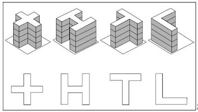
Generally speaking, it may be said that a departure from simple structural forms and layouts tends to be severely punished by earthquakes. Concentration of stress arises in buildings with complex floor plans. A complex plan is defined as that in which the line joining any two sufficiently distant points lies largely outside of the plan. This occurs when wings of significant size are oriented in different directions, for instance in H, U, or L shapes (see figure 1).
Concentration of Seismic Stress due to Complex Plans

Figure 1. Complex plan


In irregularly shaped floor plans, the wings may be likened to a cantilever built into the remaining body of the building, a point that would suffer smaller lateral distortions than in the rest of the wing. Large concentrations of stress appear in such transition areas, frequently producing damage to the nonstructural elements, the vertical structure, and even the diaphragms (that is, the horizontal resistant elements of a structure such as floors and roofs).In such a case, the solution currently used is to introduce seismic expansion joints like those mentioned in the case of long buildings. These joints allow each block to move without being tied to the rest of the building, which interrupts the cantilever effect of each wing. The joints, obviously, must be wide enough to permit the movement of each block without striking adjacent blocks.

Earthquake Requirements for Foundation and Sites


Foundation failures frequently lead to collapse or at least total economic loss of the building. Foundations should be concrete – traditional rock foundations may be used for single storeybuildings but they must be constructed to a high standard by experienced tradesmen.
For all foundations

1. Foundations should be designed to be stronger than the building elements above – we mustavoid foundation failures
2. If possible use one type of foundation throughout: e.g. piles or shallow footings• Individual foundations must be tied together in both directions
3. Ground beams should be at least as deep as columns
4. Consider settlement, especially differential settlement
5. Ensure all bearing pressures etc are similar
6. consolidation and liquefaction of the underlying soils.


Potentially Hazardous Buildings Sites


Buildings should not be constructed directly above steep slopes which are liable to become unstable, or below slopes which are susceptible to landslides and rockfalls.

Do not build too close to river banks: as a guide buildings should be at least 6 metres from a
riverbank in flood, and the floor should be at least 500mm above the flood level. For major rivers these figures are likely to increase.

Consider what happens to rain that lands on or near the building. How does it flow away from the building? Are new drains required? If so, where do the drains discharge?

Buildings must be founded in good ground. The foundations are arguably the most important
part of the building. A building on poor foundations cannot perform well in an earthquake.

The following things should keep in mind -

• The sub-grade must be sound with an allowable bearing pressure of at least 100 kPa

• Unstable ground should be avoided

• Poor soils result in a large increase in seismic forces

• The ground must be free from water at foundation level
• If surface water is present ensure suitable drainage is installed; the drain invert level must be
deeper than the foundation level


• Building should not be placed directly over fault-lines
• If a building must be constructed in a designated seismic hazard area it should be subject to
specific design.
• Site investigation is an essential part of every design

Soil types, changes in layers, depth to rock, depth of water table all effect actual loads
• Buildings must be connected to foundations (they must not be allowed to fall off
foundations).

Earthquake Performance of Brittle Materials and Its Remedy

Performance of Brittle Materials
Brittle building materials such as un-reinforced brickwork, un-reinforced concrete blockwork and un-reinforced concrete should not be used in the primary vertical load and lateral load resisting elements.

Brittle materials tend to be stiff, weak and heavy. This means they attract more lateral loads than flexible elements. Most brittle buildings material carry loads in compression only as they have low tensile strengths.

In moderate earthquakes brittle materials tend to crack; this reduces their resistance to future lateral loads.

In larger earthquakes the brittle building materials usually fail in a sudden manner without giving any warning; after failure, brittle element often cannot sustain gravity loads, meaning the structure usually collapses.
Remedy

In contrast ductile building materials are more flexible; they have the ability to sustain gravity loads without collapse (and to dissipate energy) for several cycles of lateral loads after initial yield.

Mild (and many modern high tensile steels) are ductile. Strengthening connections and columns with steel gives a structure a degree of ductility and often avoids collapse. Well-detailed timber structures are also ductile.

A fully ductile structure, usually of reinforced concrete or structural steel requires specific engineering design and detailing.Where un-reinforced masonry is unavoidable ensure the mortar used is able to accommodate movement. A mortar made from cement, lime and sand can accommodate greater movement than pure cement/sand mortar; the lower strength associated with lime mortars is rarely a problem.

Becoming Torsional Strength as Central Feature

For many years, torsion was not considered explicitly in design, its influence being absorbed in the overall factor of safety of rather conservatively designed structures. Reinforced concrete members are commonly subjected to bending moments, transverse shears associated with those bending moments, and, in the case of columns, to axial forces often combined with bending and shear. In addition, torsional forces may act, tending to twist a member about its longitudinal axis. Such torsional forces seldom act alone, but are almost always concurrent with bending moment and transverse shear, and sometimes with axial force as well.

In recent years, however, it has become necessary to take account of torsional effects in member design in many cases and to provide reinforcement to increase torsional strength. There are two reasons for this change. First, improved methods of analysis and design, such as the strength design approach now favored, have permitted a somewhat lower overall factor of safety through more accurate appraisal of load capacity, and have led to somewhat smaller member sizes. Second, there is increasing use of structural members for which torsion is a central feature of behavior, examples including curved bridge girders, ecentrically load box beams, and helical stairway slabs. Consequently, there has been a greater increase, since the 1960s, in research activity relating to torsion in reinforced concrete, and prctical desing rulels have been formulated.

Primary and Secondary Torsion

Primary torsion is sometimes called equilibrium torsion or statically determinate torsion. It exists when the external load has no alternative but must be supported by torsion. For such cases, the torsion required to maintain static equilibrium can be uniquely determined.

Followers