Foundation, Concrete and Earthquake Engineering

Cracking in Concrete Member

Cracking of concrete is a random process, highly variable and influenced by many factors. Any failure of concrete is the consequence of cracking. It impair the durability of concrete by allowing ingress of aggressive agents. With respect to appearance, cracks are also unacceptable. In addition, cracking may adversely effect the water tightness or sound transmission of structures. Cracking may occur fresh concrete due to plastic shrinkage and plastic settlement. In case of reinforced concrete members, crack generally occur at loads well below service level, and possibly even prior to loading due to restrained shrinkage. Flexural cracking due to loads is not only inevitable, but is actually necessary for the reinforcement to be used effectively.


Influence on Stress-Strain Relationship

It is interesting to note that the two component of concrete, that is, hydrated cement paste and aggregate, when individually subjected to load, exhibit sensibly linear stress-strain relation, although some suggestion about the non-linearity of the stress- strain relation of the hydrated cement paste have been made. The reason for the curved relation in the composite material-concrete- lies in the presence of interfaces between the cement paste and the aggregate and in development of bond microcracks at those interfaces. The progressive development of microcracking was confirmed by neutron radiography.Cracking in Concrete Member
The development of mocrocracking means that the stored strain energy is transformed into the surface energy of the new crack faces. Because the cracks, develop progressively at interfaces making varying angles with the applied load, and respond the local stress, there is progressive increase in local stress intensity and in the magnitude of the strain. In other words, a consequence of the development of the cracks is a reduction in the effective area resisting the applied load, so that the local stress is larger than the nominal stress based on the total cross-section of the specimen. These changes mean that the strain increases at a faster rate than the nominal applied stress, and so the stress-strain curve continues to bend over, with an apparent pseudo-plastic behavior.

When the applied stress increases beyond approximately 70% of the ultimate strength, mortar cracking (connecting the bond cracks) develops and the stress-strain curve bends over at an increasing rate. The development of a continuous crack system reduces the number of load-carrying paths and, eventually, the ultimate strength of the specimen is reached. This the peak of the stress-strain curve.


In structural design of reinforced concrete, the entire stress-strain curve, often in idealized form, must be considered. For this reason, the behavior of concrete which has a very high strength is of especial interest. Such concrete develops a smaller amount of cracking than normal-strength concrete during all stage of loading; in consequence, the ascending part of the stress-strain curve is steeper and linear up to a very high proportion of the ultimate strength. The descending part of the curve is also very steep so that high strength concrete is more brittle than ordinary concrete, and indeed explosive failure of a local part of specimens of high strength concrete tested in compression has often been encountered. However, the apparent brittleness of high strength concrete is not necessarily reflected in the behavior of reinforced concrete members made with such concrete.


Types of cracking

Non-structural cracks

a) Plastic settlement cracks

Cracking can develop also over obstructions to uniform settlement, e.g., reinforcement or large aggregate particles. This is called plastic settlement.

Details of plastic settlement

Location of appearance

1) In case of over reinforcement member it is generally located in deep section.

2) Where changing in section is inevitable they are seen frequently like waffle slabs.

3) In case of arching they appear at top of column.


Causes

Excess bleeding generally results plastic settlement cracking. Rapid early drying conditions also helps such cracks to be pronounced. Also as stated above over reinforcements and large size aggregate produce differential settlement and finally plastic settlement cracking. Plastic settlement cracking can occur also at normal temperatures but, in hot weather, plastic shrinkage cracking and plastic settlement cracking are sometimes confused with one another.

Arrival time

They are normally appeared within 10 min. to 3 hr of concrete placement.


Remedy

The plastic settlement cracking can be avoided by the use of dry mix, good compaction, and by not allowing too fast build-up of concrete. Reduction of bleeding or revibrating arrest such types of cracking.


b) Plastic shrinkage cracking

When rate of evaporation exceeds the rate at which the bleeding water rise to the surface, plastic shrinkage cracking is likely to occur. Sometimes cracks also form under a layer of water and merely become apparent on drying. The critical evaporation rate is > 1.0 Kg/m2 per hour.

Details of plastic shrinkage cracking

Size of cracks

Plastic shrinkage cracking can be very deep, varying in width between 0.1 and 3 mm, and can be quite short or as long as 1 m.

Encouraging environment

A drop in ambient relative humidity encourage this type of cracking, so that, in fact, the cause of it appear to be rather complex. According to ACI R 305 R-91 the risk of plastic shrinkage cracking is the same at the following combinations of temperature and relative humidity.

410 c (1050 F) and 90 percent.

350 c (950 F) and 70 percent.

240 c (750 F) and 30 percent.

Wind velocity in excess of 4.5 m/s ( 10mph) aggravates the situation.

Location of appearance

The loss of water from by suction by the underlying dry concrete or soil may result cracking. Diagonal cracking is observed in pavements and slabs. Over reinforced section especially steel very near to surface of slab are frequently subjected to such cracking. Random cracking may occur normal reinforced concrete slabs.

Causes

Rapid early drying generally produces this type of cracking. Low rate of bleeding as well can result cracking. As discussed previous, temperature, ambient relative humidity and wind velocity exceeding specified range results crack friendly environment. It should be remembered that evaporation is increased when the temperature of the concrete is much higher than the ambient temperature, under such circumstances, plastic shrinkage can occur even if the relative humidity of the air is high.


Remedy


Complete prevention of evaporation immediately after casting eliminates cracking. The best practice is to protect the concrete from sun and wind, to place and finish fast, and to start curing very soon thereafter. Placing concrete on a dry subgrade should be avoided.

Arrival time

They are generally appeared within 30 min to 6 hr of concrete placement.

c) Corrosion of reinforcement

The corrosion of steel reinforced concrete member by the formation of electro-chemical cell results in cracking (characteristically parallel to the reinforcement), spalling or in delamination of concrete.


This corrosion may occur due to chloride attack and carbonation.

Cracking in Concrete Memberspalling in Concrete Memberdelamination in Concrete Member
Mechanism of cracking

The corrosion of steel results cracking and further deeper propagation of cracking in two successive steps.

Firstly

The production of corrosion occupies a volume several times larger than the original steel so that their formation results in cracking. This makes it easier for aggressive agents to ingress towards the steel, with a consequent increase in the rate of corrosion.

Secondly

The progress of corrosion at the anode reduce the cross-sectional area of steel, thus reducing its load carrying capacity resulting increase in deflection encouraging cracks to be pronounced.

Location of appearance

These are normally seen in columns and beams where environment is in favor of corrosion.

Cause of cracking

Normally poor quality concrete is subjected to such types of cracking. Inadequate clear cover also makes easy intrusion of aggressive materials like chloride or results carbonation.

Remedy

Good quality concrete adding suitable admixture depending on the environment surroundings of desired concrete member. Providing adequate clear cover also discourage cracking of this type.

Arrival time

These are normally appeared after two years.

d) Cracking due to Alkali-Aggregate reaction

The most common reaction in concrete having aggregate with deleterious chemical is reaction between siliceous minerals in the aggregate and alkaline hydroxides in pore water derived from the alkalis (Na2o and k2o) in cement. This reaction can be disruptive and manifest itself as cracking.

Size of cracks

The crack width can range from 0.1 mm to As much as 10 mm in extreme cases. The cracks are rarely more than 25 mm, or at most 50 mm, deep.

Pattern of surface cracking

The pattern of surface cracking induced by the alkali-silica reaction is irregular. Somewhat reminiscent of a huge spider’s web. However, the pattern is not necessarily distinguishable from that caused by sulfate attack or by freezing and thawing, or even by severe plastic shrinkage. Within the concrete, many of the cracks caused by the reaction can be seen to pass through individual aggregate particles but also through the surrounding hydrated cement paste.

Mechanism of cracking

Consequent of the reaction stated above is formation of alkali-silica gel. These gel takes its position in the planes of weakness or pores in the aggregate(where reactive silica is present) or on the surface of the aggregate particles.In the later case, a characteristic altered surface zone is formed. This may destroy the bond between the aggregate and the surrounding hydrated cement paste.

Causes

Reactive aggregate with high alkali cement produce alkali-silica reaction and consequent cracking.

Source of Alkalis

The most common source of Alkalis in concrete is cement. Alkalis become concentrated in some locations, at the expense of others. Such concentration may be caused by moisture gradients or by alternating wetting and drying. The alkalis may also become concentrated by an electric current passed through the concrete which may occur when cathodic protection is used to prevent corrosion of embedded steel.
The additional sources of Alkalis in concrete include sodium chloride present in unwashed sand dredged from the sea or obtained from the desert. Other internal sources of alkalis are some admixtures, especially superplasticizers, or even the mix water. The alkalis from these sources, and also from fly ash and ground granulated blast furnace slag, should be included in the calculation of the amount of Alkalis present.

Location of Appearance

It is normally appeared in damp location.

Remedy

It has been found that expansion due to the Alkali-silica reaction can be reduced and eliminated by the addition to the mix of reactive silica in a finely powdered form. This finely divided siliceous material added to the coarse reactive particles already present would reduce expansion, although the reaction with the alkalis still takes place. These pozzolanic additions, such as crushed pyrex glass or fly ash, have indeed been found effective in reducing the penetration of the coarse aggregate particles. The fly ash should contain no more than 2 to 3 percent by mass of alkalis.
Pozzolanas in the mix are beneficial also because they reduce the permeability of concrete and therefore reduce the mobility of aggressive agents, both those present with in the concrete and those which may ingress. Furthermore, C-S-H formed by pozzolanic activity incorporates a certain amount of alkalis and thus lowers the value of PH. With the decrease in PH alkali-silica reaction rate also decreased.

Silica fume is particularly effective because the silica reacts preferentially with the alkali. Although the product of reaction is the same as that between the alkalis and the reactive silica in the aggregate, the reaction takes place at the very large surface of the fine particles of silica fume. In consequence, the reaction does not result in expansion.
Ground granulated blastfurnace slag is also effective in mitigating or preventing the deleterious effects of the alkali-silica reaction. It should be noted that the presence of ground granulated blastfurnace slag results in a reduced permeability of concrete.
Lithium salts may inhibit also expansion reactions.

Time of Arrival

These cracks normally appeared after 5 years of construction.


e) Crazing
It is an another type of early cracking like plastic shrinkage cracking and plastic settlement cracking which can occur when the surface zone the concrete has a higher water content than deeper in the interior.
Size and pattern of cracking
The pattern of crazing looks like an irregular network with a spacing of up to about 100 mm (4 in). The cracks are very shallow and may not be noticed until etched by dirt; apart from appearance, they are of little importance.
Location of appearance
Walls and slabs normally subjected to crazing cracks.
Causes
Over trowelling and impermeable formwork are primarily results these cracking. Rich mix associated with poor curing also results these cracking.
Remedy
Properly designed concrete with adequate curing reduces such cracking. Poor finishing avoiding over trowelling reduces crazing to great extent.
Time of arrival
They are normally appeared within 1 to 7 days, sometimes crazing may takes much time.

Opening in Slab and Beam

Beam
Most reinforced concrete members are statically indeterminate because they are part of monolithic structure, i.e., in this form of building construction, slabs are cast monolithically with a beam-and –girder floor framing that carries the floor load to columns. A beam is a flexure member. It may be of steel, wood or any other structural materials. Reinforced concrete beams are nonhomogeneous in that they are made of two entirely different materials. A flexural member should suffer a axial compression force less than Ag fc´/10. The member must be at least 10 in wide and its clear span should be least 4 times the effective depth and the width-to-depth ratio should be at least 0.3.

Slab
Slabs are used to furnish a flat and useful surface in reinforced concrete construction. It is broad, flat plate, usually horizontal, with top and bottom surfaces parallel or nearly so. It may be supported by reinforced concrete beams, by masonry or reinforced concrete walls, by structural steel members, by directly by columns or continuously by the ground.

Slabs in which the deflected surface is predominantly cylindrical is called one-way slabs spanning in the direction of curvature. This condition arises when slabs are supported on two opposite sides, and those supported on all four sides with the longer span greater than twice the shorter span and also in cantilever slabs. In many cases, rectangular slabs are of such proportions and are supported in such a way that two-way action results. when loaded, such slabs bend into a dished surface i.e., an any point the slab is curved in both principal directions, and since bending moments are proportional to curvature, moments also in both directions.

Concrete slabs may in some cases be carried directly by columns, without the use of beams or girders. Such slabs are called flat plates. In some cases, to reduce the stresses due to shear and negative bending around columns, a thickened slab region in the vicinity of column and flared column tops are incorporated. Such construction is called flat- slab construction.

Occurrence of Opening
Slabs

In almost all constructions, slab system include openings. These may be of substantial size, as required by stair-ways and elevators shafts, or they may be of smaller dimensions, like those needed to accommodate heating, plumbing, and ventilating risers, floor and roof drains, and access hatches.

Beams

These may occur when opening in slabs pass through the effective flange width of T-beams, for installation of building services. Opening are also frequently provided through beam web.


Code’s Recommendation for Placement of Opening

Slabs
As far as possible, opening in slabs should be located in zones where shear stresses are small and bending moment are below maximum. However, small opening for pipe sleeves etc. can be made anywhere in slab. In case of slabs supported directly by columns, from structural view point, they are best located well away from the columns, preferably in the area common to the slab middle strips. Opening of any size may be provided in slab systems if shown by analysis that the design strength is at least equal to the required strength and that specified limits on deflection meets. For strength the strip method is appropriate. Opening in Slab and Beam

Code Requirements
13.5.1 Opening of any size are permitted in slabs if analysis shows that both strength and deflection are acceptable.

13.5.2 In lieu of special analysis as required by 13.5.1 opening may be provided in slab systems without beams only in accordance with the following.

13.5.2.1 Opening of any size may be located in the area common to intersecting middle strips.

13.5.2.2 In area common to intersecting column strips, not more than 1/8 the width of column strip in either span shall be interrupted by openings.

13.5.2.3 In the area common to one column strip and one middle strip, opening size is limited to 1/4 the width of column strip in either span.

Beams

In regions of small shear, as near the middle of a beam span, a horizontal pipe sleeve is not serious. Elsewhere, shear strength must be closely watched and in many places bending strength as well.

Strip Method to analyze Opening
The strip method was first developed by Hillerborg, and later Wood and Armer analyzed the method critically and performed test on slabs designed by this method. They found that a design made by the strip method and reinforced exactly according to moments found, was an exact solution.

The strip method is the simplest one for slabs on simple supports, but continuity can be handled on a basis similar to limit design. The most difficult slabs for this method are slabs supported on columns. For such a case, Hillerborg developed the advanced strip method, using a rectangular element carrying load in two directions to a support at one corner of the element.

The equilibrium equation for slabs is

Opening in Slab and Beam

All elements of this equation, except w, follows the Timoshenko’s notation.

i.e., Mx and My = bending moment about respective directions.

Mxy = twisting moment.

and w = load per unit area on slab.

Hillerborg designs the slab to make Mxy unnecessary, that is he assumes Mxy = 0 and than apportions the load to ∂²Mx/∂x² and ∂²My/∂y², usually at a particular spot wholly to one or to the other. This particular apportionment is more of a convenience than a necessity, however, loads in a particular area are assign to particular slab strips and continuity of the resulting moments and shear must be carefully maintained. Apparent discontinuity in torque or deflection may be disregarded, but a discontinuity in moment or shear is not permitted. Both elastic and plastic analysis concepts are permissible in evaluating moments on strips.
Opening in Slab and BeamOpening in Slab and BeamOpening in Slab and Beam
The suitability of the method for slabs with opening is a strong point in its favor. This method have been using for many years by designers, designing by their ‘feel’ for the way the load has most apt to be transferred to the supports. As slabs are normally considerably under-reinforced, it is possible to use certain strips near the opening as small beam simply by increasing the local reinforcement. If the opening is so large that even extra slab steel is inadequate to care for the moment, a real beam is needed around one or more sides of the opening, quite probably spanning to the edge beams. The assumed “beam strips” are drawn as dotted around the opening and the point of inflection as suggested by Wood and Hillerborg are added on the slab. Then different moment for different strip is calculated. Depth can be fixed from loads (moment and shear). The reinforcement should be arranged in bends corresponding to the strips used, this calculation is simple.

Defection at service load must be considered in checking serviceability. In any actual design the service load is available, and it should be on the safe side to use the strip service load moments with EI based on
the cracked section.

Treatment for Opening

Larger opening should be framed by beams to restore, as nearly as possible, the continuity of the slab. The beams should be designed to carry a portion of the floor load, in addition to loads directly applied by partition walls, elevator support beams, stair slabs etc. But, in case of flat plate construction, opening near column render difficulties.

Effects on Strength and Treatment

Slabs

The effect of openings on the shear strength as well as flexure action (in case of large opening) of slab must be investigate carefully. The effect becomes severe when the openings are within the column strip areas of slabs or within middle strip areas when the opening are closer than 10 times the slab thickness(10h) from a column, measured radial.

To account for reduction of shear strength, it is considered that a portion of the critical section b0 is ineffective which is enclosed by straight lines projecting from the column centroid to the edges of the opening. If two much resisting perimeter is lost, the designer must be sure adequate tow-way bending is really present; otherwise the lower shear permitted in beams become the limiting values for the slab.

For slabs with shear reinforcement, the ineffective portion of the perimeter b0 is one-half of that without shear reinforcement. One-half factor is interpreted to apply equally to shearhead reinforcement and bar or wire reinforcement.Opening in Slab and Beam
Opening in Slab and Beam
Code Recommendation


13.5.2.4 Where opening in slabs are located at a distance less than 10 times the slab thickness from a concentrated load or reaction area or when opening in slabs are located within column strip, the critical sections shall be modified as follows:

1) For slabs without shearhead, that part of the perimeter of the critical section that is enclosed by straight lines projecting from the centroid of the column, concentrated load or reaction area and tangent to the boundaries of the opening shall be considered ineffective.

2) for slabs with shearheads, the ineffective portion of the perimeter shall be one-half that defined in (1) above.


Beams

Large opening in beams are particularly weakening. They destroy beam action and force the reduced section to act such as a Vierendeel truss ( a truss without diagonals). In such a truss the average bending moment over the length of the opening is resisted by axial compression one chord and tension in the other, with these two forming a couple in the case of pure flexure. Where shear is present the change in the moment over the length of the opening superimpose a reversed bending resistance in each chord, the total of the four end moments on the chords equaling the external shear times the length of the opening. How the shear and these reverse moments are shared by the chords depends on the relative chord stiffness.

Thickening of edge of opening

In case of larger openings, the edge of the slab around the opening may be thickened to enable them to behave like trimmer beams for taking up additional moments and forces. If opening reduce a critical design section for moment, must be maintained by providing extra depth to offset the reduced width.

Function of Steel

The steels used around opening tie the free ends of the bars which are trimmed to form opening. It also serve as reinforcement to make the opening stable against deformation or any other types of failure. This bars take care of the loss of steel in a slab on account of forming opening. Diagonal bars provided in corner control the cracking that will almost inevitably occur there.

Steel Requirement

Slabs

With regard to flexural requirements, the total amount of steel required by calculation must be provided, regardless of opening. Any steel interrupted by holes should be matched with an equivalent amount of supplementary reinforcement on either sides, proper lapped to transfer stress by bond.

If minor cracking at the corners of an opening is objectionable, it is always advisable to add one or two diagonal bars at each corner, especially at large openings. Bars are always desirable around Window and door opening in concrete wall slabs, because such reinforcement helps to take care of shrinkage stresses.

Code Requirement


Slab

13.5.2.1 In case of opening in intersecting middle strips, total amount of reinforcement required for the panel without opening is maintained.

13.5.2.2 In case of opening in intersecting column strips, an amount of reinforcement equivalent to that interrupted by an opening shall be added on the sides of the opening.

13.5.2.3 In case of opening common to one column strip and one middle strip not more than ¼ the reinforcement in either strip shall be interrupted by openings. An amount of reinforcement equivalent to that interrupted by an opening shall be added on the sides of the opening.

Beam

11.3.1.3 For members with significant axial tension, requires all shear to be resisted by stirrups (none assign to the concrete).

Steel Arrangement

Reduction in critical design section for moment due to opening, can be overcome providing more closely on each side of the opening to maintain the necessary As. This is possible only when opening is possible to locate where moment is well below the compression capacity of the slab, thereby leaving the arrangement of reinforcement as the only problem. Of course, shear strength must be maintained, but this is rarely a problem except near the columns in flat slab type, as noted previously.
Opening in Slab and BeamOpening in Slab and Beam
The arrangement of bars around any but minor opening can constitute a real problem. Bars running perpendicular to the face of an opening are not fully effective when simply cut0off at the opening. This is acceptable if there is a beam at the opening to act as reaction for the slab. If there is no beam it is better to fan the bars out or splay them to go around the opening. If fanning or splaying leaves too wide an area without steel, extra bars can be placed parallel to the side of the opening, as indicated.

Intensity of earthquake

The earth suffers a highly variable intensity of earthquake from time to time. Some of them are catastrophic resulting complete destruction of building and ground, while some can’t be felt, only can sensitive instrument can predict. So, once an earthquake struck, it is important to know about severity of it and impact of it on the community to get prepare for aftershocks and future trembling. In order to have a comparative study of earthquakes and to define areas of known intensities, it is essential to establish a measure or a scale of reference.

Several classification of earthquake intensity have been used. To the engineer, a classification based on the maximum acceleration of the ground is of most interest. The acceleration due to gravity is 9.8 m/sec. It should keep in mind that the earthquakes may have different degree of accelerations as well as that different geological conditions produce different effects.Niigata Japan earthqauke

Measure of Intensity

To develop a effective scale to measure intensity, the data required are


a) the acceleration produced

b) the extent of damage caused to buildings and ground surface.

Historical Development of Scale

Initially a scale of earthquake intensity having ten divisions was given by Rossi and Forel, which was based entirely on the sensation of people and damage caused. However it has been modified by mercalli and further by Wood and Neumann in 1931, which will be discuss in this article.


Modified Mercalli Intensity Scale

Collection of Data


It measures the impact of an earthquake by sending out trained observers to look at the damage done to the built environment and the earth (landslides etc.) and at the reaction of people to the event.

Application of Collected Data
 

Instrumental records of earthquake vibrations are supplemented by information gathered from individuals through such types of questionnaires. Many data that are not brought out by instrumental methods are thus assembled; and information is gathered also from areas where no instruments have been established.

Details of Modified Mercalli Intensity Scale

This scale defines the effects of an earthquake over a limited geographical area. Intensity scales assign whole numbers usually from 1 to 12, expressed in Roman numerals. An intensity I means the earthquake was not felt, while XII means absolute and total destruction. The descriptions used to assign earthquake intensity values on a M.M.I scales are shown in following table :


Advantage

The advantage of using the M.M.I scale is that it relies on the observations of people experiencing an earthquake instead of scientific instruments. This allows seismologists to assign earthquake intensities to seismic records, an activity that helps them to estimate seismic risk for earthquake sites today.

Disadvantage

The fact that the Mercalli scale relies on peoples observations is a disadvantage because this makes a evaluation subjective and dependent upon the social infrastructural conditions of a country. This scale also not very helpful in an area with little human habitation, since no one would be around to experience the earthquake.

Example

In case of intensity value VII on the M.M.I scale not effective or should be rewritten for a country without chimneys and automobiles.


Latest scale of intensity

Now a scale , called European Macro seismic Scale (1992) is widely used which has been developed and tested over period of years by a working group of the European seismological commission. The EMS makes the imprecise and subjective nature of assigning intensities more robust and straight forward with regard to earthquake effects on human, objects and buildings.


Isoseismal lines

The intensity of earthquake decreases with increase in distance from the centre of disturbance. This decrease is inversely proportional to the square of this distance. In an area, subjected to earthquake, the places suffering same intensity can be determined. A line joining points of same intensity is called an ‘Isoseismal Line’. If the focus of earthquake is a point, the area enclosed by an isoseismal is circular whereas an elongated zone or line results a elliptical area.

Magnitude of an Earthquake

An earthquake is the result of a sudden release of energy in the earth’s crust that creates vibration radiating all directions with a decreasing rate from the centre of disturbance. When an earthquake occurs, it is important to know where the seismic event took place, how intense it was, and what its impact was on the built environment. The more we know about earthquakes and how and when they occur, the more we can do to lessen their effects on our communities.

Measure of Energy

Whenever there is an earthquake, it indicates the some of the strain energy held within the body of the earth has been released in the form of rupture. The released energy travels around in the form of earthquake waves, causing displacement of the ground surface. In a low-intensity earthquake this displacement is small, while in a high intensity earthquake it is large. Thus, the displacement is directly a function of the amount of energy released during an earthquake.

If ‘ a’ is the maximum displacement recorded, then magnitude ‘M’ is given by the relationship

M = log10 a +c

According to Richter the relation of magnitude with the energy released ( E in ergs) is given by the equation

log10 (E) =5.8+2.4M.

Details of Scale
In this scale, one can measure size of earthquakes based on recording of ground motion by instruments. The Richter scale value is calculated by measuring the maximum recorded amplitude of a wave. This measurement quantities i.e., the ground motion and the energy released at the source of an earthquake, which is referred to as its magnitude. The Richter scale is open ended and logarithmic (base 10) and accommodates the wide range of ground motions, appeared during arrival of a p-wave or surface waves and measured applying a standard correction for distance to the epicenter, that earthquake can caused. This means that there are no upper and lower limits to the scale and that every time the magnitude goes up by one unit, the amount of energy this represents increase thirty times. Each unit of the Richter Scale represents a 10 times increases in wave amplitude. Richter magnitude is expressed as an Arabic number, which helps to distinguish it from the Marcalli scale.

It is observed that a magnitude less than 5.0 is of no engineering interest as it does not have any adverse effect at all.

Energy in Relation to Magnitude
An earthquake of magnitude 4.0 on Richter scale would release energy equivalent to 6 tons of TNT, or about as much energy as a small atom bomb. A magnitude of 3.0 is equivalent to only 397 pounds of TNT. It should be noticed that 397 pounds is 30 times smaller than 6 tons. In the following table the different magnitude equivalent to TNT energy are stated clearly:


Historical Development of Scale
The first magnitude scale was devised by Charles Richter in 1935. Scales today are based on various aspects of the seismograms as told by the following names:
      a) Body-waves magnitude
b)
Duration magnitude
c)
Moment magnitude
Jamaica uses the duration magnitude and moment magnitude. Moment magnitude is the most true indication of the size of an earthquake because it is based on the amount of movement of fault. 

Moment Magnitude
Moment magnitude is the measure of total energy released by an earthquake. It is based on the area of the fault that ruptured in the quake. It is calculated in part by multiplying the area of the fault’s rupture surface by the distance the earth moves along the fault. 

Richter Scale in Relation to Mercalli Intensity Scale
 
The Mecalli scale describe the effect of the energy, while the Richter scale describes the amount of energy associated with an earthquake. So both the scales are used to measure earthquake.


Example:

In 1989 an earthquake struck Loma Prieta which had a magnitude of 7.1 on Richter Scale and VII on the Mercalli Scale. This quake produce moderate loss of life (67 people died) and the built environment suffered relatively little damage. Most of the building affected in the Loma Prieta earthquake had been built with seismic provisions to reduce damage.


In contrast, the 1988 Armenian earthquake measured almost the same magnitude (6.9) on the Richter, but its Mercalli measured intensity was XI. More than 50,000 people lost their lives, and the built environment was almost totally destroyed. 


The damage done by the Armenian earthquake was greater than that done by the 1989 Loma Prieta earthquake, although the magnitude was almost the same.


As the quality of the built environment is a big factor in the number of lives lost and the amount of damage done in an earthquake and intensity is a function of loss and destruction. So the magnitude of an earthquake does not always correlated with the intensity or impact. The local codes also keeps focus on the intensity rather than magnitude.

Ground Motion During Earthquake

Earthquake are the sudden, rapid release of energy stored in rocks and becomes perceptible by the constant motion of the earth's surface. The earth's rock layer is broken into large pieces. These pieces are in slow but constant motion. They may slide by each other smoothly and almost imperceptibly. From time to time, the pieces may lock together and energy that accumulates between the pieces may suddenly released. The energy that is released travels through the earth in the form of waves. People on the surface of the earth than experience an earthquake.


Ground Motion

The energy released at each material point within the three dimensional volume that ruptures at the fault, results seismic waves which produce motion to earth’s surface. The motion at any site on ground is random in nature with its amplitude and direction varying randomly with time as these waves arrives at various instant of time having different amplitudes and carry different levels of energy. Knowing how, fast, for how long, and how much the ground moves during an earthquake is important for estimating how ground motion will affect the built environment. Seismologist use several concepts to express these measurements:

1) Acceleration
2) Duration
3) Velocity
4) Displacement

Acceleration

A series of vibrations are created when seismic waves move through the ground. These movements are transmitted into dynamic loads or inertial forces that cause the ground and any thing attached to it (i.e., the built environment) to vibrate in a complex manner. These inertial forces cause damage to buildings and other structures. Inertial forces are created when an outside force tries to make an object move or change its rate of travel.
Acceleration is the rate of change of motion. The variation of ground acceleration with time recorded at a point on ground during an earthquake is called an accelerogram. The nature of accelerogram may vary depending on

- Energy released at source
- Type of slip at fault surface
- Geology along the travel path from fault rupture to the earth surface
- Local soil

They carry distinct information regarding ground shaking; peak amplitude, duration of strong shaking, frequency content ( amplitude of shaking associated with each frequency) and energy content (i.e., energy carried by ground shaking at each frequency) are often used to distinguish them.

Normally acceleration is not associated with buildings since building is not expected to move. During an earthquake, however, inertial forces may cause the upper part of the building to sway while the foundation remain stationary, or they may cause whole building to “move”. Structures built in seismically active areas must be built to withstand predicted acceleration levels.


Duration


The duration of ground motion is very important because the destructive effects increase greatly with increase in length of duration. The damage will occur the whole time the ground is moving. So more damage is likely to occur the longer an earthquake lasts. In predicting the amount of potential damage that could occur in a specific should include the duration of ground motion.


Velocity


Velocity is mathematically related to acceleration. Velocity is the speed of an object at an instant in time. Velocity is quickly becoming as important as acceleration in determining the building damage. Consider an example: if your car decelerate suddenly, the inertial force may cause your head to hit windshield. The velocity at which your body id traveling at the instant your head hits the windshield determines whether you get a little bump or a fractured skull. For a building, this could mean the difference between superficial damage and building collapse.


Displacement

Displacement is the distance an object is moved from a resting position, such a how far a building is moved or displaced from its foundation. Seismologist use measurements of displacement to judge the impact of an earthquake on a community.


Conclusion

None of the scales (The Richter Magnitude Scale and The Mercalli Intensity Scale ) used to measure earthquake, are not enough to develop a seismic resistant design method or further development of scientific study. The Richter scale does not give ground motion information that is important for designers. The Mercalli scale is subjective and does not cover many new kinds of construction used today. Together with theses information, scientists can define an earthquake having following information:
- Where seismic events takes place
- How large it was
- What its impact was on the built environment.

Failure of Dam

Dam
A dam can be defined as an obstruction or a barrier built across a stream or a river. At the back of this barrier, water gets collected, forming a pool of water. The side on which water gets collected is called the upstream side, and the other side of barrier is called the downstream side. The lake of water which is formed upstream is often called reservoir.

Function of Dam

The function of dams is to block the flow of a river creating an natural storage tank for the now trapped water. It provides water for irrigation and water supply for domestic use. It can improve navigation and create a reservoir of water for to supply industrial uses, generates hydro-electric power, create recreation areas. It is also a habitat for fish and wild life. The most important function of dam is to control flood. It can control effluent from industrial sites such as mines or factories.

Dam Failure

A functional dam needs to be strong enough to hold back its reservoir and it needs to be able to pass flood water through the structure during heavy rains and periods of increased run-off. Dams are classified by the material and design used in construction and the failure is also depends on such classification. The Federal Emergency Management Agency (FEMA) defines dam failure as a catastrophic type of failure, resulting a sudden, rapid and uncontrolled releases of confined water.


The failure of the dam may be caused either due to bad workmanship or due to faulty design or due the occurrence of unanticipated floods. Luckily, these disasters have been comparatively rare in this century. Dams used to give away in olden times, but due to engineering advancement in modern times their failure has been considerably reduced taking care of design, keeping in view the various forces which are going to face, proper and rational design, good supervision and constant vigil and watch during maintenance periods ensures their safety. The Boulder Dam on Colorado River in U.S.A can not fail in one attempt, how furiously these river may try to move their foundations. But sometimes we have to pay for this confidence with tragedies.
Malpasset Dam
Malpasset Dam

The "Reyran" river flowing well few hundred meters below the dam.

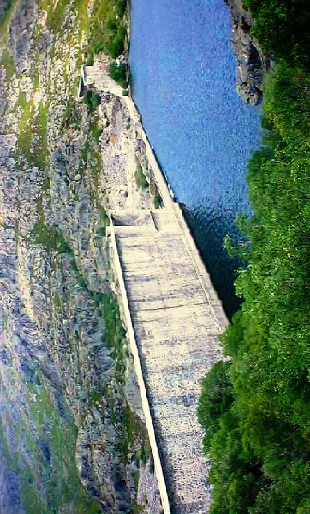
In 1954 the Malpasset Dam, a 200 feet high arch dam on the Reyran river, was completed. This dam failed in December 1956 causing 421 persons to die in floods. This was due to failure of foundation.
Vega de Tera Dam
Vega de Tera Dam
A very confident dam called Vega de Tera Dam in Spain failed in January 1959. The town Rivaldelago was fattened. Telephone poles were snapped like matchsticks. With in moments, 123 villages were drowned. Several hundred luckier ones were saved, but were rendered homeless. This time this dam was not built strong enough to bear the full weight of its intended reservoir. Heavy rains wrecked it.
Vega de Tera Dam
Vega de Tera Dam
Sometimes excessive and unanticipated earthquakes may result failure to a dam. In 1968 earthquake, the Koyna Dam in india was at the verge of failure. The engineers saved that dam by toiling hard day and neight.

Shakidor Dam Brust

The other failures are South Fork Dam due to spillway design error, Shakidor Dam due to extreme rainfall and Dale Dike reservoir, Taum Sauk pumped storage plant due to human, computer or design error.


Leading Cause of Dam Failure

a) Hydraulic failures

More than one-third of all dam failures have been attributes to these causes. These type of failure may occur due to the following reasons:

1) Overtopping

When water levels rise rapidly and without adequate warning due to flash floods, heavy rains, a landslide in the reservoir that creates a tsunami, or if a dam upstream collapses, overtopping occurs and rise in level of level of a reservoir exceeding the capacity or height of the dam. If the spillways become blocked with debris, like silt, mud or trees, or the spillway gates are not operated properly and water can not be released, there is a danger that the water level in the reservoir will rise higher than the crest of the dam and spill over resulting overtopping.

2) Erosion of Upstream Face

Wind produced waves near the top water surface and try to notch out the soil from the upstream face and may even, sometime cause the slip of upstream slope.

3) Cracking Due to Frost Action

The upper portion of dam may subject to heaving and cracking of soil due to frost action with dangerous seepage and consequent failure.

4) Erosion of Downstream Face by Gully Formation

The erosive action on downstream face of moving water from heavy rainfall, may lead to formation of gullies on the downstream face, ultimately leading to the dam failure.

b) Foundation Defects

This failure is responsible for one-third of all dam failure of whole world. The main cause of concrete dam failure is a problem with foundation. Dams built on slopes must be properly engineered to avoid issues with instability or landslides. Only the weight of a dam structures has an impact on the ground underneath. If this weight is not properly taken into account in the engineering of the dam, the ground underneath can settle unequally and compromise the foundation. Any event causing the movement of a foundation, such as earthquake, can also result failure of the dam’s foundation. High uplift pressure and uncontrolled foundation seepage can also lead the dam foundation to failure.

c) Seepage Failure

The semi-permeable dam like embankment type can be failed when too much seeps or leaks through the structure. Controlled seepage or limited uniform seepage is inevitable in all earth dams and ordinarily it does not produce any harm. Uncontrolled or concentrated seepage through the dam body or through its foundation results piping. Piping is the progressive erosion and subsequent removal of the soil grains from with in the body of the dam or the foundation of the dam. More than one-fifth of all failure of dam occur because of these reasons.

1) Piping Through Foundation

Water, through the foundation of dam, may start seeping at a huge rate when highly permeable cavities or fissures or strata of coarse sand or gravel are available in the foundation of the dam. This concentrated flow at a high gradient, may erode the soil. This leads to increase flow of water and soil, ultimately resulting in a rush of water and soil, thereby creating hollows below the foundation. The dam may sink down into hollow so formed, causing its failure.
Piping Through Foundation

2) Piping Through the Dam Body

When the concentrated flow channels get developed in the body of the dam, soil may be removed in the same manner as was explained in the foundation piping, leading to the formation of hollows in the dam body, and subsequent subsidence of the dam. These flow channels may develop due to faulty construction, insufficient compaction, cracks developed in embankment due to formation of settlement, shrinkage cracks, animal burrows etc.
Piping Through the Dam Body
4) Armed Conflict

The dams creates dangers in wars, especially in modern atomic age. The resultant failure of such a dam will create catastrophes, but also it will get contaminated by radioactivity from which there could be no escape.

This is an important point which results stress on the host of the dam. In World War II, British Royal Air Force Dambusters operate raid on Germany, in which three German dams were selected to breached in order to have an impact on German infrastructure and manufacturing and power capabilities deriving from Ruhr and Eder River.

To protect possible destruction on the civilian population and the environment, the rules of International Humanitarian Law ( IHL) are made and dams are defined as object not to be attacked. During armed conflict, dam is to be considered as an “ installation containing dangerous forces”. A protective sign consisting of three bright orange circles placed on the same axis is provided to facilitate the identification.

5) Other Reasons

Dams which are improperly maintained or built with inadequate materials or unsound design can result in structural weakness that lead to catastrophic dam failure.


Dam failure

REINFORCEMENT REQUIREMENT OF PILE

The amount of reinforcement and its arrangement vary with the loading condition and installation and driving condition. The amount and arrangement of reinforcement for different types of pile are discussed below briefly.
Precast Pile

Longitudinal Reinforcement

The minimum amount of longitudinal reinforcement should be 1.5% of concrete section. At least 4 bars have to provide in a symmetrical pattern.

Lateral Tie Spacing

At each end of pile lateral tie reinforcement consisting of 6mm dia or larger have to place at a spacing not more than 75 mm center to center, or an equivalent spiral shall have to provide through a length equal to at least three times or the pitch of spiral may be increased to 300 mm.

Clear Cover

The cover of concrete over all the reinforcements including ties, should not be less than 70 mm anywhere through out the length of piles.

Cover should be measured clear from the main or longitudinal reinforcement.

Cast-in-situ Piles

- Minimum vertical reinforcement in bored cast-in-situ piles shall be four 13 mm dia bars and embedded at least half of the pile.

- Reinforcement should be assembled and and tied together and should be placed in the piles as a unit before the reinforced portion of the pile is filled with concrete.

- When hollow stem auger is used to install piles, the longitudinal steel reinforcement should be placed through ducts in the auger prior to filling the piles with concrete.

- All pile reinforcements should have a concrete cover of not less than 65 mm.

Under-reamed Bored Cast-in-Situ Piles

Longitudinal Reinforcement

- Minimum longitudinal reinforcement in stem shall be 0.4 %.

- Reinforcement is to be provided in the full length.

- Minimum 3 bars o 10 mm of diameter mild steel or 3 bars of 8 mm diameter high strength steel be used.

Transverse Reinforcement

Transverse reinforcement should be provided with bars not less than 6 mm in diameter and at a spacing not less than the stem diameter or 300 mm, whichever is less.

In case of cohesion less soil, under-reaming should not be done in both above and below ground water table.

The minimum depth of under-reaming bulb shall be either 2.75 m or below the level of stabilized moisture content, whichever is deeper.

Under-reaming Compaction Piles

Vertical reinforcement

Minimum four 12 mm dia bars should be provided, but for piles of length exceeding 5 m and diameter exceeding 375 mm, a minimum of six 12 mm dia bars shall be provided. For piles exceeding 400mm in dia, a minimum of six 12 mm dia bars shall be provided.

Transverse Reinforcement

The circular stirrups of such piles shall be provided with a minimum of 8 mm dia bars.

Followers