Himalayan Thrust Faulting Released Energy (M-7.8 Nepal Earthquake)

A devastating earthquake hit Nepal having magnitude 7.8 April 25, 2015 with epicenter 77 Km North West of capital Kathmandu. Many sites are discussing about earthquake damage, casualties, rescue and future steps to overcome this crisis. We will discuss here rather technical information.


We know within earth crust, movement of plates (major or minor) produce strain energy; when the energy becomes large enough to generate rupture, the released strain energy produces earthquake.

Tectonic cause of M 7.8 Nepal earthquake April 25, 2015

Since 1988 there have no record of major quake in this region in earthquake history. The region means subduction zone where Eurasia plate is ridding over India plate. These two plates are converging at a rate of (40-50) mm per year.


The Nepal-Bihar earthquake (1934) claimed around 10,600 fatalities having magnitude of 8.0. These two earthquake was located 240 Km away from this recent earthquake in Nepal.


Though major plates we subducting past each other at major plate boundary in this region, the thrust of such magnitude are rare in history. Only four quakes were recorded having magnitude 6 or more around 250 Km radius of this present epicenter.


The April 25, 2015 earthquake in Nepal is found compatible with subduction thrust between Eurasia and India plates. This quake was a shallow earthquake and the location was 28.147°N 84.708°E, the intensity measured at Kathmandu VII, Patna V and Dhaka VI.

How to Mitigate Foundation Settlement on Collapsible Soil?

Different methods are suggested to handle collapsible soil. In most problematic soils, it is the best way to remove all soils that can produce large foundation settlement and replaced by soil that is safe against settlement.


Does any soil type is safe? Same soil having in different state can be safe or unsafe. Say sand, cohesionless soil, is considered safe if they are in dense condition. Again sand having moisture and critical grading can suffer extensive settlement under vibration.
Vibro compaction to densify cohesion less soil

We know the vibration is usually considered from earthquake shaking, the settlement term is not perfect here it is better describe by liquefaction. We have published many posts about liquefaction in this blog; you can visit them from top menu and left menu.


A sand deposit that have no moisture or have relatively less moisture never subjected to liquefaction. So safe soil is relatively variable term depend on many factors. We use this term here as recompaction of sand is required to have a denser pack.


The collapse potential of collapsible soil can be reduced by using compaction grout. We know penetration of moisture result severe settlement in collapsible soil. So we can introduce water by flooding or forcing water to penetrate like providing wells to make the deposit collapse before foundation construction as the soil skeleton reach to equilibrium condition under this method.


In choosing foundation systems if possible select deep foundation. It is the safest way but most costly method to mitigate foundation settlement in this type of soil. Replacing deposit of collapsible soil is considered cost effective when they remain in shallow depth. Otherwise replacing and flooding techniques both is not valid.
Post tensioned mat foundation

Deep foundation like piles can be rest on stratum below collapsible soil. Other foundation system like mat foundation or post tensioned foundation can also be designed to resist expected settlement in collapsible soil. Mat foundation is effective to reduce differential settlement. We have published many posts about design, construction and computer modeling of raft or mat foundation.
Sinkhole in gypsum based collapsible soil

We know collapse in natural soil or fill of the same are triggered with the penetration of moisture. Now if we can check moisture to penetrate the triggering mechanism becomes inactive and foundation will remain safe against settlement.


The common sources of moisture infiltration are water from

• Irrigation
• Leak in water supply line

• Breaking down of water supply or sewer line

• Ponding of rain water around or near foundation

• Any type of surface runoff

• Leaks in pools


So immediate repairing of any leak and break down in water or sewer line and providing effective drainage around building site to avoid ponding of rain water, in one word, all possible method providing moisture barrier will make your foundation and structure safe against collapsible soil.

Concrete/Grout Strength for Foundation Construction (IBC)

Dear reader in our previous posts we have provided information about concrete strength for foundation and piling work according to different code. Here we will learn about IBC requirement for this foundation construction materials.


When concrete is poured in deep foundation special requirement for workability is important. We know in deep foundation like piling work, one of the most popular pouring techniques is through funnel hopper.


The compressive strength specified (minimum value) in IBC-2009 are as follows:
Concrete compressive strength specified (minimum value) in IBC
Concrete poured through funnel hopper from top of foundation element, should be proportioned such that proper cohesiveness of the mix is achieved. The minimum slump recommended as per IBC is 102mm equivalent to 4 inches.


There have also a maximum limit too, that is less than 204mm equivalent 8 inch. In some cases grout has to pump; the mix should be designed to have pumpable workability. Dear reader we already have discussed about pumpable concrete mix.


DES: In deep foundation like piling work, one of the most popular concrete pouring techniques is through funnel hopper.

How to Determine Shear Wave Velocity for Earthquake Design, IBC

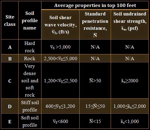
In our last post we have learnt that IBC classify site as Class A, Class B, Class C, Class D, Class E and Class F for earthquake design. Of these except class F, all are depend on shear wave velocity. In other building code, shear wave velocity is also important to classify site depending on soil properties.


Site class A and class B are defined as rock (soil profile), class C also include soft rock and dense soil. At first we start with site class B. it is recommended in code that shear wave velocity to measure on site.
MASW for analysis of record of geophone
Alternatively, seismologist/ engineering geologist or geotechnical engineer can estimate shear wave velocity on competent rock having moderate weathering and fracturing.


Site class C can be determined by determining value of shear wave velocity. But the rocks that are relatively weathered and fractured highly and also softer, we can classify them as class C.


The soil profile representing site class A is hard rock. Here also shear wave velocity is recommended to measure on the site. Alternatively, a value, measured in soil having identical soil profile of same type of rock in identical formation having a same or more fracturing or weathering condition, is recommended in code.

Site class F is not dependent on shear wave velocity, this mostly include collapsible, sensitive, liquefiable and very plastic soils. In determining site class A, where soil profile shows a continuation of hard rock up to 100 ft (30480 mm), we can determine shear wave velocity by extrapolation from surficial shear wave velocity.
Seismic crosshole test method for shear wave velocity
IBC also prohibit to classify site as class A or class B, when there have soil layer of more than 3048mm between bottom of mat foundation or spread footing and rock surface; it should keep in mind that site as class A or class B are considered rock category.

Dear reader in site classification for site class C, class D and class E where soft rock to soft soil profile exist, S, N̅, N̅ chand s̄u used as per code, considered for upper 30480mm (100ft)of site profile. In such cases, 100ft site profile have several distinctive layer of different soil or rock and they are subdivided into respective layers and designated as ranges of number form 1-n. n is the bottom layer and n distinct soil or rock layer are considered in upper 30480 mm profile.
Determining Shear Wave Velocity
Where
i represents a layer between 1 and n
Vsi=shear wave velocity (ft/sec)
Classification of site for earthquake design
di= thickness of a layer within upper 30480 mm profile

Site Classification for Earthquake Design, IBC

The site classification is usually related to earthquake design. In our few upcoming posts, we will try to introduce IBC requirements in designing foundation in relation to earthquake perspective. Depending on soil properties of construction site, sites are classified as

• Class A
• Class B
• Class C
• Class D
• Class E
• Class F

definition of site classification according to IBC are presented below:
Site Classification for Earthquake Design

Site class F:


If any profile of soils have any of following or combination of following characteristics:


1. Soils susceptible to potential collapse or failure under earthquake loading like liquefiable soils, clay having high sensitive and quick clay, collapsible loosely cemented soils.


2. Clays having high organic content and or peats having thickness of layer more than10 feet


3. Clays having very high (PI>75) plasticity; layer thickness more than 25 feet.


4. Stiff clays (soft to medium) of very thick (greater than 120 feet).


In defining site classification we depend on v̅S, N̅and s̄where
 
v̅SShear wave velocity of soil at site (ft/s)


N̅Resistance against standard penetration

s̄uUndrained shear strength of corresponding soil (psf)

Though site class E is defined based on shear wave velocity, standard penetration resistance and undrained shear strength, if any profile with more than 10 feet of soil having the following characteristics should also be treated as site class E:


Earthquake site class E (soil profile)

So shear strength, resistance against standard penetration and shear wave velocity are required to classify site according to IBC. In some class like E and F plasticity index, moisture content, organic content are important though these properties are relatively simple to determine.

In some cases, when we have no sufficient details about site soil, it is recommended to define site as site class D. But we can assume this only when geotechnical data or building officials ensure that site do not fall in the class of E/F.

When a site cannot be classified as Class F, this site can be taken as site class E under following conditions: 
 
Earthquake site class E

Reinforcement Requirement for Micropile (IBC)

Dear reader in our previous post we have discussed about materials required for micropile construction. There we have learnt about cement, admixture, filler and water quality for micropile construction. We will learn about reinforcement in this post.


Reinforcement/reinforcing bars should be essentially deformed bars complying with

-ASTM A615 grade 60

-ASTM A722 grade 150

Or AASHTO M275
Bar coupler in reinforcement of micropile
According to International building code steel reinforcement provided in micropile should be designed to bear not less than 40% of compressive stress.


Any portion of micropile or micropile as a whole has been grouted in open hole without permanent or temporary casing in soil and where suitable means to verify hole diameter is not available during grouting, the reinforcing steel should be designed to bear total compression loads.


We know deep foundation element may suffer tension loading with usual compression load; this is due to lateral forces from various sources and in rare case direct pullout force.


Sometimes bars coupler is used in reinforcing bars; they should develop to their ultimate stress without having any sign of failure; here we also discussing about tensile loading.


In case of compressive loading, the coupler, where required, should compatible with overall requirements of reinforcement performance and should have efficient and effective load transfer mechanism.

Installation Record for Micropile

Installation record of micropile should follow specific steps, and proper monitoring of installation of any foundation especially deep foundation is very important. Dear reader in this blog we are publishing may FAQ of micropile design, manufacture and also installation, many are still to come.


Following records should be prepared by respective division who is responsible for respective job for owner or other authorized professional. It is recommended to complete records within 24 hours after completion of installation of each micropile. The maximum information that should include in the records is as follows:
Settlement testing of micropile

A. Duration of pile drilling and observations too (for example flush return).

B. Information of rock and soil encountered which should also include description of individual stratum and water table etc.

C. Approximate elevation of final tip

D. Design load

E. Description of behavior of unusual installation and conditions

F. Any deviation encountered during installation from the expected parameters

G. Attained grout pressure as applicable

H. Pumped quantities of grout

I. Pipe materials along with dimensions

J. Details, analysis and records of micropile test.


In addition to these records, as -building drawing describing location of piles, depth of them, details of composition of pile and inclination have to be submitted within specified calendar days as required by specification, obviously before completion date.

Materials Required for MicroPile Construction

The materials and products required for micropile construction are:

A. Water

B. Admixture

C. Cement

D. Filler

E. Bar reinforcement

F. Pipe or casing

G. Plates and shapes

H. Centralizers

I. Corrosion protection materials or method


We will discuss about only materials except bar reinforcement and pipe or casing. They will be discussed in next post. Corrosion protection and plates and shapes will be discussed in upcoming posts.

Grouting during micro pile construction


Water


Dear reader, we know grout is applied in micropile construction and water is essential element of grout. Water used to mix grout should be

-Potable

-Clean

-Free from deleterious substances which may affect steel or grout quality as well.


If potable water is not available, used water should be tested for approval according to AASHTO T26.

Admixture


We all know about admixtures for concrete and sometimes for mortar, but what should be use of admixture in grouting? The objectives of applying admixture are to

-Control bleeding

-Control shrinkage

-Increase of improve flowability

-As water reducer

-Elongating setting time

-Provide washout resistance

Admixtures in concrete, mortar and grout help to overcome many limitations of cementitious materials as discussed in previous part.

Requirements for Admixture :


All admixtures to be used in grout should comply with the requirements provided by ASTM C494, alternatively AASHTO M194.


When sealed encapsulation is filled with grout, the expansive admixture is generally used in grout. Admixture selected for grout should be compatible with it and recommendations of manufacturers are followed for mixing to ensure proper dose and quality of mixing.


Truck mounted grouting system for micropile
The admixture required for controlling bleeding, reduction in water content, elongating setting time and improving flowability of grout should be used after reviewing and acceptance of owner. Admixture that contains chlorides should not be used in grout as it threatens the longevity of micropile reducing durability.


If required or building official have any doubt about admixture, appropriate field tests are conducted say for expansive admixture-field tests in fluid and setting of grout.

Cement:


All cement to be used in micropile construction should confirm ASTM C150 or AASHTO M85 Type I, Type II, Type III and product should be of same manufacturer. However brand/type of cement may be changed during construction of project; in this case some tests like grout mix tests should be conducted to assure consistency in quality of construction and in-situ performance too.

Fillers:


Sometimes filler materials like sand are used in grout and before use should be approved by owner. Fillers are required in special situations like

-Larger voids are found

-To limit travelling distance of grout