How does Diesel Hammer Work in Pile Foundation Operation?

Precast piles are driven with the help of pile driver/hammer to reach expected foundation depth. Different types of hammers are used in pile foundation construction. We have already learned about all types of pile hammer, briefly, in our previous post. Here we will discuss about diesel hammer.


The hammers used, now-a-days, have large engine of two-stroke facility. A cylindrical apparatus connects to top of pile. The weight that drives the pile, with ignition energy, consists of this apparatus and piston. As we go through the topics we will learn about the apparatus gradually.


Runbang DH50 diesel hammer
At first the weight is raised with auxiliary means, which may be a crane or any other means. Usually a crane holds this pile driver. While raising the weight air entered in to cylinder by suction.


The weight is released quickly to drop over pile. This quick release results compression of air trapped during raising. This compression raises the temperature of air to reach ignition point of fuel.


Obviously the fuel is diesel. There have facility to inject diesel fuel to such heated air. The ignition of mixture (air and fuel) generates energy which is then transferred to pile head enhancing the driving energy.


The ignition energy not only transferred to pile head but it drives the weight to its previous falling height. So the auxiliary means to raise the weight back its position is not required after initial application. While rising, the cylinder again draws fresh air and cycle stated above kept running.
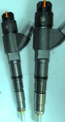

Diesel injector These cycles can be stopped willingly by pile operator or automatically when fuel injection is stopped due to run out of it. So far we have discussed about operating principle of diesel hammer. Now we will discuss about some details of apparatus and mechanism as well.

The hammer operation starts with raising piston called ram to a designated point while the raising system automatically releases ram. The ram falls by gravity over the pile top. There have mechanism with the ram and fuel ignition system.


When ram falls, this mechanism automatically gives live to fuel pump. This pump has facilities to insert fuel to such amount to result ignition successfully with optimum efficiency.


While piston falls, it closes the exhaust system through which the system draws fresh air into it. This results an entrapped condition of air. In the impact block the fuel pump releases fuel into ball pan.


Driving of pile with diesel hammer
The fuel discharged into the impact block is metered such that it provides specific amount of force to pile and at a time rebound the piston to this automatically release point of raised position.

As discussed above, while piston falls, it blocks exhaust system to entrap air. This entrapped air is compressed by the weight of piston. The compressed air produces a preloaded force of around 44,000 lbs.


The preloaded force holds firmly the impact block against pile through driving cap. While the piston exerts force the pile becomes mobilized from it position overcoming inertia and skin friction. Now our aim is to exert extra pressure by the explosion of fuel in the diesel engine.


Working principle of diesel pile hammer
From the previous topics of relative efficiency we have learned that the blow interval develops inertia and friction resistance which have to overcome by next blow and after overcoming the pile get mobilized. Here we have advantage of initial mobilization of pile by preload force and when fuel energy results pressure, pile moves without overcoming this resistance. Obviously in the next blow this resistance is again developed.


When piston strikes impact block, atomizing fuel pump and exerts downward movement to pile due to impact. The compressed air at ignition temperature of fuel results explosion which exerts greater force than that of impact and generates further downward energy to already moving pile.

The pile results rebounds on the piston and it moves towards upward. While moving up back, the exhaust system which was previously blocked in compression stroke is released. Thus the gases and explosion force is released to atmosphere. This system again draws air to its cylinder and when energy of upward movement is diminished, the piston falls again and the cycles are continued.

Why is Grouting Applied in Stabilizing Foundation Soil?

In various cases both from economy and practicability; where deep foundation cannot be adopted and as well excavation of entire problem soil or soft soil deposit is not possible, we, foundation engineers, look for stabilization of soil in improving its engineering properties.


We have discussed earlier that there have many stabilization options like, cement stabilization, lime stabilization, bituminous stabilization, chemical stabilization and mechanical stabilization. Stabilization with grouting is another method of stabilization in foundation engineering. We have discussed a related term jet grouting and other grouting methods by injection to renovate slab-on-grade foundation and regaining its previous serviceability conditions.
Dam repairing with pressure grouting
Here in this post we will discuss about suitability of grouting stabilization method.

As discussed above, this process is done by injecting a stabilizer in pressure through the soil. The soil suitable for this stabilization is high permeable soil as the stabilizers are generally of high viscosity and injection pressure makes them reach this grout to the further end of pores.


Raising effort of pavement slab sunk at junction with Polyurethane Foam Injection
As clay soils have low permeability, naturally this method is not suitable for cohesive soils of less permeability. The stabilization method we discussed in previous posts, use more or less direct blending. But this method involves injection with pressure and grout viscosity and injection pressure are the design criteria to avoid grout loss. We have discussed about grout loss in our previous post. You can read this for more information.


So this method is costlier than other stabilization methods. This method does not disturb the soil below much or almost zero. The projects where disturbance of soil to be stabilized, is not acceptable, this method is most suitable. Normal application is stabilization of soil enclosed by existing building like slab-on-grade. In stabilization of dam, that have underneath pervious stratum such method is suitable.

What are Filter Criteria for Basic Performance of Geotextiles in Soil Improvement?

Geotextiles are extensively using in many civil engineering projects where soil improvement or slope stability is of great importance. In 1958, geotextiles were first applied as filters when traditional filters of designed graded coarse grained soil were replaced by it. Now-a-days geotextiles are using in many slope stabilization and erosion recovery problems.


As a filter, geotextiles should be properly designed to ensure adequate or designed retention of erodible materials to be retained and provide sufficient discharge capacity throughout designed life of structures. Now we will learn basic filter criteria that are considered in selecting geo-textile for filter purposes. These criteria are:


Providing geotextile in stabilizing of soil slope
a. Retention requirement which considers the prevention requirements of migration of particles to be retained through geotextile.

b. Permeability requirement which ensures flow a liquid through the geotextile. Generally it is expected to establish a free flow condition. Our aim is to retain soil particles but provide a free passing out of liquid i.e. water in common cases.

c. Clogging prevention requirement, this requirement includes the performance of geotextile regarding above two criteria remain satisfactory throughout life cycle of structure i.e. the geotextile performs well with satisfying retention and permeability requirements.


But above three criteria of geotextile can be satisfied only by controlling distribution of pore sizes throughout the geotextile and largest openings of pore. Dear reader in united states the term AOS or O95 are used regarding geotextile opening size. AOS stand for apparent opening size. We will learn about AOS and O95 in our next post.

Foundation Problem with Organic Soil

Organic soil is a problematic soil. The soil that have properties that may result to serious foundation problems, where there have large uncertainly of its behavior and difficulties in sampling is exist, these are problematic soil.


So we have learned about problematic soil with above definition. Now we will learn about mineral content and origin of organic soils. Organic soils are enriched with organic contents which are generally formed due to decomposition of organic materials. In many cases, these soils may exist below other soil mass. Generally they are found in marshy place and at top soil. We will discuss about the classification of organic soil in our upcoming posts.


Fibrous organic soil
Now we will discuss about the problems with organic soils, especially foundation problems. We know that any organic materials have a characteristic of decomposition. In contact with air they become oxidized and results a destruction of slow rate. Thus the volume of organic matters is reduced resulting a compressibility property.


They may shrink excessively with compaction. Though oxidation is stated above but anaerobic reaction may be happened in most case they are main reaction. These soils have large moisture content but this is not observed in their plasticity. Organic soils, in some cases, are also corrosive.


So this highly compressible soil shows subsidence in slow rate that may produce many foundation problems. Foundation settlement, cracking in structural joints and members, sometimes corrosion in foundations, and as usual damaging utility system buried or in ground surface, are common problem with these soil. In the next post we will discuss about identifications, difficulties in sampling and testing, and classification of organic soil based on different parameters.

Different types of pile hammer for pile foundation

Pile is a deep foundation system to accommodate access structural load to the relatively firm stratum through end bearing or skin resistance and sometimes with the combination of both. We usually choose this type of foundation when loose soil deposits serving low bearing capacity for shallow foundation, or sometime problematic soil like expansive soil, collapsible soil, and also organic soil are present. Though in case of expansive soil the pile in many cases, are designed for anchorage purposes.

The names we familiar with are:

a. Drop hammer 
b. Single-acting steam hammer 

c. Double acting steam hammer 

d. Diesel hammer 

e. Vibrating hammer
Drop pile hammer for pile foundation

Single-acting steam pile hammer pile foundation operation At first, we will discuss drop hammer. In general, we are familiar with driving pile with blow; the exception is vibrating hammer. The driving operation with a hammer providing blows to piles is called pile driving operation and the equipment is termed as pile driver. We may need to drive pile both vertical and inclined direction. Normally guides are used to align the pile driving.

When a hammer is lifted to desire elevation with a rope and let to provide blow on the top of pile by free fall, the hammer is called drop hammer.

When a hammer is lifted with the help of steam pressure and let to provide blow by gravity fall; the hammer is termed as single-acting steam hammer. Hammer using steam energy, like previous hammer; have also another verity known as double acting steam hammer.

When steam energy is used to lift hammer and as well steam pressure is used to enhance downward energy, the hammer is called double acting steam hammer. From the name we can realize why this is double acting steam hammer.

Diesel hammer is lighter than double-acting steam hammer and can easily be transported. It is also operated at slow rate then double acting steam hammer. Diesel hammer is a unit which containing a fuel tank and essentially injectors.

Double-acting steam pile hammer pile foundation operation
Diesel hammer have a very large diesel engine. Obviously modern hammers are two-stroke engine. The weight consists of piston and the cylindrical arrangement that is placed on pile top.

The manufacturer of hammer specifies the rate of energy to be exerted by this pile hammer.Let consider Vulcan(016) pile hammer, which specifies the energy of 48750 ft-lb. sometimes in case of large diameter piling work more energy is required. The example is offshore drilling platform where large energy of driving is required and a capacity of 180,000 ft-lb has been rated by some manufacturers.

Vibratory pile Hammer for pile foundation operation
Now we will discuss about a pile driver that has less energy loss than our conventional hammer. This is vibratory driver. This driving technology is extensively used by Russian piling engineers. The arrangement, called oscillator, is mounted by crane or other means on the top of pile to be driven. The oscillator has pair of eccentric masses which is driven by electric or hydraulic motor. Such operation of oscillator is called vibratory driving.

Volumetric Batching and Possible Error in Concrete Proportioning

We have already learned that volumetric batching is not frequently used in concrete industry because of its incorrect measuring of ingredients of concrete mix. With this problem, in Indian subcontinent this method of batching is used even in important projects. Due to improper batching it is often allowed in small or less important construction project. Now we will learn the evil of such batching method.


If the granular portions of concrete mix are measured by volume, the resulting concrete may have different properties for a same ratio of batching when other conditions are considered same (placing handling, compaction, finishing etc). This is due to measuring error of materials, as same volume of granular part may have different weight depending on water content and voids in particles.


gauge box for volumetric mixing of concrete Consider two same volume of sand, one in moist condition and other in dry condition. A certain volume of dry compacted sand has much weight than same volume of moist loose sand. So when we measure one cubic meter of granular materials, we actually measure an indefinite quantity. For this reason concrete batching on the basis of weight is the only method for accurate proportion of a mix.


In the previous post we have learned about way of measuring cement. So we are not discussing this term here. There has no problem with water. Water can be measured by kg or liters as 1 kg of water have volume of 1 liter. Water measured in term of water/ cement ratio. Definitely the measuring criterion of cement is its weight.


But when volumetric batching cannot be avoided, we will use certain techniques to minimize errors and taking assumption. Here gauge boxes are introduced having different designed volume depending on volume of cement per bag. Dear reader we will discuss this elaborately in the next post.