How is Better Drainage Achieved by Sand Blanket in Cohesive Soil?

We know cohesive soils are less impermeable. The degree of impermeability depends on the texture and mineral structure of soil particles and also on many other factors. We have already discussed about consolidation of soil. The aim of using sand blanket is to facilitate better consolidation. A better consolidated soil deposit suffers less settlement.


In a saturated deposit of cohesive soil, fills or soil preloads are provided for this purpose. These fills or preloads increase the length of drainage path and this increment in drainage path perhaps occurs at top of fill. As we know, the path length of drainage of saturated soil determines the time required for consolidation and these is desired to be the shortest that can practically be achieved.
Applying sand blanket over collector fabrics to facilitates consolidation soil
In case of site where water table is found very near to ground surface, the site is prepared with monoslope(where with of site is small) or shallow ditches to collect squeezed water is provided in series(for a large site). These slopes are provided creating a graded cutting. For this purpose in site grades (if any) are used for economy and ease of work. Then sand blanket is provided. 


The blanket is provided by placing a (100-150) mm thick sand layer on both collecting ditches, stated above, and over the site. After providing sand blanket preloading is applied. The soil that get consolidated by preload, release water as soil get squeezed and this water is collected through ditches or from edge of sand blanket and flows to disposal edge. These process accelerate drainage as we know the sand has large co-efficient of permeability.

Unpredictability of Settlement of Shallow Foundation on Collapsible Soil

In the previous post we have discussed about the identification and mitigation methods for collapsible soil related problems. Shallow foundation on unsaturated collapsible soil can perform satisfactorily for sometimes. But these soil suffer sudden settlement of sufficient amount. This accidental settlement is induced due to sudden occurrence of water source which results flood through soil.


The volume decrease that occurs in collapsible soil under imposed load when wetted is dependent on following factors:

Collapsible soil foundation problem

The difficulties in estimating settlement of collapsible soil include:

a. Variation of grading of soil

b. Variation of cementation of soil

These variations results variations in soils properties in both vertical and lateral directions. The most disturbing factors are these changing may occur within few centimeters and unpredictable occurrence of water source. The uncertainty arises as lateral and vertical extent of these variations cannot be predicted certainly.

What Mitigation Measure Should be Taken for Using Collapsible Soil as Foundation Bed?

Several mitigation options are used to deal with collapsible phenomenon of these soils. We are providing a list of mitigation measures below. Any of them or combination of them can be used in field application depending on the characteristics of soils. Soils are investigated carefully before application of these measures. Houston (1996) provides some measures that are provided below:


1. The soils that are sensitive to moisture have to remove.

2. The removal should follow replacement or providing compaction to them.

3. Restricting wet environment

4. These soils may be stabilized with chemical or grouting

5. Prewetting techniques sometimes is used successfully

6. Providing controlled wetting

7. Dynamic compaction of soil

8. Deep foundation like pile/pier foundations

9. Providing foundation that is not susceptible to differential settlement

The measures stated below are suitable only when wetting moisture is occurred from ground surface or from near ground surface infiltration. These measures are:


1. Restricting wetting from irrigation

2. Restricting landscape vegetation near structures

3. Surrounding paved surface is sometimes expected to restrict infiltration of moisture. The extent of paved surface is determined by economy and practicability.

4. Sewer lines and water lines should be kept leak free. For this purpose double pipes and sometimes troughs are used.

5. Forming a low permeable soil to have a barrier to wetness penetration by removal and or replacement and compacting surface layer of foundation soil. In providing barrier for water, soils that are insensitive to moisture is used.


Risks of collapse are avoided as the wetting reduced or controlled to desire degree. Analysis should be performed to compare total cost involved for these measures to economical loss due to suspected collapse settlement of designed or repair of foundation of structures and various alternatives are compared considering these. 

How can Explosion Generated Liquefaction be Used for Compaction of Foundation Soil?

We all know any type of explosion generates vibrations and shock waves. Sometimes this energy can be used in compaction of foundation soil. The energy performs compaction like vibratory equipments used for usual compaction.


At first we will learn what types of explosives are used and where it should be buried. The explosive charges generally contain 30% gelatin dynamite of special types having ammonite and 60% dynamite. Normally the charges place at 2/3 of the thickness of required stratum to be densified for founding building structure.


The charges should be placed at (3-8) m interval and for a particular location 3-5 blasts are usually generated to have required compaction. 
Blasting explosives for compaction of foundation soil
Now we will know the mechanism of compaction. This method of compaction is suitable for cohesionless soil of fully saturated condition. Shock waves generated by explosion results liquefaction to sand resulting a densification of the surrounding depositions. But in case of partial saturated soil capillary action obstruct the densification tendency by preventing soil particles to come close. So this method is not useful for partial saturated soils.


Now we have to know the zone of influence of explosion densification. Up to 25m depth is considered effective in blast operation. Uppermost soil up to 1 m depth is displaced in random manner leading improper densification. This random densified zone is compacted by usual compaction method (roller).


The following expression gives an idea about radius of influence(R):
Explosion compaction for foundation soil
Where M=mass of explosive charges (kg)

C=constant (considered 0.04 in case of 60% dynamite)

Foundation Settlement Due to Consolidation of Compacted Fill

In many practical purposes foundation engineer uses fill to raise the plinth level and for many other reasons. This fill is compacted to desired percent compaction to have better bearing stratum for founding building structures. Now in this post we will discuss about settlement generated by consolidation of compacted fill.


We all know that compacted fill usually undergo some degree of subsidence. This is due to readjustment of grains due to self-weight. There have two forms of settlement. One is settlement of underlying soil on which the compacted fill rests. Another settlement is due to settlement of compacted fill itself. The settlement of underlying soil will not discuss in this post.


Compacting a landfill for providing firm foundation of pavement  We will now learn about the factors that controls the settlement process:

a. Type of soil particles and particle packing; in one word soil fabric. The soil fabrics in relation to compaction effort.

b. The amount of water used during compaction process and future changes from provided moisture content.

c. The height of fill (i.e. self weight from thickness of fill) and superimposed load from foundations or from any other surcharges.


Cracking in concrete pavement due to settlement of compacted fill
Depending of depth of fill and above factors the fill may settle from 60 mm to 500mm and even more.


The settlement of compacted fill due to consolidation involves future mass saturation and can take a time of the order of several years. Geotechnical engineers may predict such types of consolidation in laboratory. Soil sample to filled is compacted to required moisture content and field density and put under consolidation testing device to test primary compression and secondary compression and swelling properties as well.

How is Precompression Applied in Compaction of Foundation Soil?

Precompression is a process in which a soil mass to be used as foundation bed is preloaded to improve its properties and then design loads are applied. It is normally used in improving properties of cohesive soils.


The preloading results settlement to soil before construction process starts. Preloading is applied with a mass of earth fill which is left above area for a long period. The period is determined by the adequate settlement or desired settlement. Now question is how settlement is calculated?


Vertical sand drains used for precompression of foundation soil
A system of monitoring is provided by using settlement plates with piezometers to check the progression of settlement of foundation soil. Sufficient geotechnical investigation for the work site is performed to have a sound idea about magnitude and rate of settlement to be applied as described above. The preload should select carefully to avoid shear failure. The stability of soil deposit beneath preload should be evaluated carefully.


When a sufficient settlement is achieved, the construction is started removing preload. Sometimes to accelerate settlement a system of vertical sand drains are provided. In the previous post we have discussed about vertical sand drain. This process of compaction is used successfully for clays, silts, sanitary-landfills and organic soil.

How to Compact Concrete in Junction between Fresh Concrete and Existing Hardened Concrete?

In the previous posts we have discussed about stages of manufacturing concrete. We have learned many aspects of compaction stage of concreting process. In our recent we have discussed about insertion spacing of vibrator head in concrete. Here we will learn about method of compaction of fresh concrete in junction with fresh hardened concrete.


In many practical purposes we have to cast concrete in junction with existing old or recently hardened concrete in case of construction joints. It is observed that when fresh concrete is placed above or beside the existing concrete, there have some defects. This is due to insufficient vibrating of concrete layer near hardened layer. In many instances the flexible shaft becomes inactive when it gets contact with hard surface. In this situation the following procedure can be adopted.
Defective concrete construction joint due to lack of proper vibration
The surface of hardened concrete is prepared by removing greasy or loose particles, removing laitance and roughening it. Then the clean surface is wetted with sufficient water. A grout of cement-sand having 1:1 proportion with creamy consistency is applied over the cleaned wet surface of existing old concrete and then fresh concrete is poured with subsequent vibration. This procedure produces a better solution for concreting in conjunction with hardened concrete.

What is the Relationship between Entrapped Air to Strength-Durability of Concrete?

The aim of compaction is to remove entrapped air. The entrapped air reduces the strength of concrete considerably. A study shows that concrete strength is reduce to 30% with 5% voids in the mix due to improper compaction. A reduction of more than 50% is found due to presence of 10% voids. A figure is provided to explain air-void to reduction in strength relationship in percentage.


For higher strength concrete mix designer is now using low water-cement ratio and problem arises there. Low water-cement ratio produces a less workable concrete if some type of water reducing admixtures or additives are not used. A less workable concrete trapped more air than a higher workable concrete mix i.e. stiff mix of concrete have more entrapped air requiring high efforts to remove this entrapped air from mix by compaction.
Air void to Loss of strength relationship for concrete
From the above figure we can understand the importance of 100% compaction and 0% air void achievement in concrete.


As durability is concerned, 100% compaction is also required for durability of concrete as well as strength of concrete. Now-a-days designers give more priority to durability of concrete than strength. The presence of void increases permeability of concrete and permeability opens the way to entry aggressive chemicals. Thus deterioration of concrete and reinforcement as well takes place.


Therefore an optimum water-cement ratio have to set to have a fully compacted dense concrete with the help of available, affordable, accessible and reasonable compaction that take long compaction and not supposed to have segregation of constituent material and to chose economical compaction options. It should keep in mind that only a maximum possible driest mix with 100% compaction having 0% air void produce a concrete of maximum strength and durability.

What to Do for Grout Losing in Mudjacking for Slab Foundation?

At first we will know about consistency of grout used for mudjacking of foundation. The grout consists of soil-cement and water or soil-cement-lime. In normal cases consistency is adjusted by solid and water ratio. Thinner grout travels over greater area and may escape from work area through bleeding. But thicker grout is restricted to limited area due to its consistency. But in some cases, thicker grout also may escape from the area intended to be grouted to have specific foundation repair to slab foundations. The situations are no or shallow perimeter beam, foundation having concentrated load which have less bearing area like interior fireplace etc. If thicker grout cannot solve the problem then the following methods are undertaken.


a. Stage pumping
Ongoing Mudjacking for a settled pavement slab
This is a method of pumping grout intermittently i.e. grout supplying is stopped after some grout is supplied to provide a period to thicken the grout and sometimes this period may be the time of initial set. This process of stage pumping is used repeatedly. But it should keep in mind that grout must not set in hose and shutdown time is calculated considering this fact.


b. Containment by shoring

In this method sheet piles of plywood or other suitable materials are driven around slab perimeter in to the soil strengthened by suitable bracing. Care should be taken not to escape grout through joints in sheet piling.


c. Underpinning

Underpinning is used to lift slab to support structural loads. The lifted slab up to desired level facilitates mudjacking into soil perimeter without any resistance to flow grouts. We have discussed resistance to mudjacking in the previous post. It is worth mentioning, that raised slab without shoring may result sometimes a way of escaping grout. Considering this situations sometimes sheet piling also associated with underpinning.

What is Percent Compaction of Soil in Foundation Engineering?

In the previous post we have discussed about compaction and consolidation of soil. In this post we will have an idea about a comparison between dry density in field to maximum dry density.


In determining percent compaction, dry density rendered or found in field, (through different methods of compaction or natural soils) and maximum dry density is compared. The maximum dry density can be determined by modified proctor test or standard proctor test. The expression is

Percent compaction of foundation soil
Where δd =dry density


Thus percent compaction of a soil mass is a ratio of dry density in the field to maximum dry density.
Pneumatic tyred roller for foundation soil compaction
In case of cohesionless soils, a percent compaction of 100% or sometimes even more can be achieved using vibratory rollers, pneumatic tyred rollers or other means of vibration application compactor machine.


In case of cohesionless soils special means of compaction with necessary moisture content can produce up to 95% percent compaction.


The term percent compaction is very important in geotechnical engineering as engineers sometimes increase bearing capacity to considerable amount and they specify this defining compaction methods and evaluate the compaction efficiency by percent compaction. When a desired percent compaction is achieved, the foundation engineers can fix foundation size and other parameters using increased bearing capacity of foundation soil.

How can Black Cotton Soil be Classified?

In the previous post we have discussed about lime treatment for black cotton soil and the related chemical reactions to change their molecular structure. To perform a treatment to black cotton soil, it is important to classify the soil. Depending on the classification, the treatment process is chosen and in case of same treatment process geotechnical engineers can determine the degree of treatment. Black cotton soil can be classified, depending on plasticity index and expansion index.


We know black cotton soil produce problems in road pavement, airfield, retaining structure, canal, and underground plumbing and sewerage premises and as a whole all types of foundation are affected by it. In case of building structures it not only disturbs in design phase but also produce mishaps to construction and even in some maintenance work. 


Oedometer for One Dimensional Swell or Settlement Potential of Black cotton soil
In 1995 wray reported that-

Plasticity index less than 20 is considered less expansive.
Plasticity index >20 to <40 is considered expansive.
Plasticity index >40 to 60 is considered highly expansive

Plasticity index 60>is considered very expansive.


Many engineers use expansion potential of black cotton soil i.e. expansion index (EI)

Expansion index of ≤50 is considered less expansive.


Expansion index ≥91 is considered as high expansive.


Expansive soils of any kind obviously have a minimum and maximum moisture content limit. Whatever happened, either swelling or shrinkage, depend on this critical limit. So knowing the actual type of black cotton soil is important to have a proper foundation design prediction. An elaborate discussion and tables will be provided in next post.

How does Calcium Oxide Make Expansive Soil Suitable for Shallow Foundation?

The major difficulties of placing foundation on expansive soils are the swelling properties of them. We all know that expansive soil mostly contains clay particles and we have discussed in many posts about Montmorillonite and kaolinite. Now our aim is to provide an idea to reader about the calcium treatment for such clay particles.


The purpose of treatment of expansive soil with calcium oxide is the change in its mineral structures and a suitable change in mineral structures leads a expansive soil to behave better as founding bed for building structures. In the process of treatment lime results a chemical reaction of cation exchange where the ions attached to crystal of clay are substituted by the positive atoms in the solution. Calcium oxide provides a cementing agent in the expansive soil which renders a strong and firm soil. The smaller particles are get together to form larger particles as the positively charged particles react with opposite charged particles.

Ongoing Calcium Treatment of Black Cotton Soil
Calcium oxides treatment thus results a treated expansive soil of greater strength and low susceptible to shrinkage and swelling process. By this the major limitation of expansive soils are removed. The expansive soils spread all over the world and results many difficulties to foundation. In United States many structures are suffering by this soil. In India this soil is found mostly in the form of black cotton soil. We have published many posts about black cotton soil and with its suitable foundation guidance. In Africa there have also the same problem of black cotton soil.

What are the Spacing Requirements for Vibrator Insertion in Concrete?

In the previous post we have discussed about different types of vibrator, vibration techniques for different concrete member and also about over vibration. In this blog we will try to provide every information about concreting process. In this post we will learn how spacing of insertion of vibrator is fixed.


There have not many requirements for vibrator head insertion. But to explain this we have to learn about action range of vibrator. Action range of vibrator can be predicted for a vibrator operation by noticing following things:


a. Raised air bubbles around vibrating head

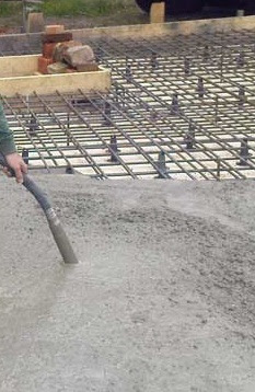
Mechanical compaction of concrete with vibrator
b. Observing a shining thin film formed around vibrator head.


The action range of vibration depends on the

1. Vibrator type

2. Composition of concrete

3. Concrete workability


Our aim is to provide efficient vibration to expel entrapped air to form a compact mass of concrete. For this purpose, the vibrator insertion point should be spaced such that action range is overlapped to some extent.


In case of workability of concrete having compaction factor of 0.78 to 0.85, the vibrating head is inserted typically (35-90) cm apart. The spacing that is fixed from above considerations is applied uniformly in entire concrete surface to have a uniformly vibrated concrete.

What is the Specific Heat of Concrete?

In the previous post we have an overall idea about thermal properties of concrete. Of those parameters we will discuss not about specific heat. Specific heat is a basic term of physics, we will not go through the definition. We will now learn about influences of specific heat of concrete.


Specific heat is found to be increased with the increase in moisture content of concrete. But mineralogical properties of aggregate have no influence on specific heat. This property increased with the increment of temperature of concrete. But an opposite response is observed with density of concrete i.e. it increases with the decrease in concrete density.


For ordinary concrete, specific heat may vary from 0.20 to 0.28 Btu/lb per 0F. A term named thermal absorptivity is used in quantify the fire effects on concrete.


The expression is


Thermal absorptivity= √(Kρc)


Where K=thermal conductivity of concrete

ρ=density of concrete

C=specific heat of concrete

Form this expression, we can conclude, this thermal property is both depend on specific heat and thermal conductivity. So both thermal conductivity and specific heat are important to determine behavior of concrete in extreme temperature like fire and explosion generated heat.
Failure of both concrete core and perimeter columns of World Trade Center
Thermal absorptivity of normal weight concrete is 6.44 Btu/ft2h1/2per0

Thermal absorptivity of light weight concrete is 2.73 Btu/ft2h1/2per0F for concrete of density 90.5 lb/ft3

Why Should Thermal Properties of Concrete Consider in Structural Design?

Besides other properties of concrete, thermal properties are also important in  analysis and design of concrete structure. In this blog we will discuss about thermal conductivity, thermal diffusivity, specific heat and thermal expansion of concrete. These four main thermal parameters are mostly used in analysis and design and in sometimes used during idealization of structures.


First we will learn about the parameters in brief. Thermal conductivity is a measure of the conducting ability of heat of concrete. Thermal diffusivity is a rate that defines the temperature changing capacity of concrete within its mass. As we know specific heat is the amount heat required to create unit change in temperature.

Failure of both concrete core and perimeter columns of World Trade Center
Thermal conductivity and thermal diffusivity are related to formation of temperature gradients in concrete, early stage cracking in concrete, thermal strains and warping of concrete. Thermal insulation is also related to these properties.


Most of the materials used in engineering purposes have positive thermal expansion co-efficient. Concrete also agree with this trend. This important property is used in determining keeping provision for support movement of bridges. It has influence on both vertical and horizontal movements. The expansion property is also used in design and detailing of contraction and expansion joints for concrete members. Structures that are indeterminate should be checked for deformations due to variation in temperature. Many structural softwares provide facility to check response from temperature effects. In prestress concrete industry this property is also considered with care. Thermal gradient of concrete is also depends on it.

September 11 Twin Tower attacks
In special applications behavior of concrete at high temperature is very important like taking considerations for the impact of fire and explosion generated heat. In the previous post we have discussed about fire and explosion characteristics of concrete. From these, some links are provided here: 

How is Grout Contained in Mudjacking of Slab Foundation?

The containment term is arisen in foundation mudjacking due to bleeding of valuable grout from work area (slab perimeter). In case of grouting to longer distance a thinner grout is used to migrate to a greater area. This thinner grout, in most cases, is escaped from work area resulting an ineffective mudjacking and subsequent resettlement of slab foundation hampering warranty if provided any. To avoid these situations sometimes a thicker grout is used. But sometimes this thicker grout may also escape from designed bearing area. In these situations some methods for containing grouts are adopted.

These are:

a. Shoring to Provide Containment: sheet piling of suitable materials like plywood etc are used to provide containment. Sheet piles are buried around slab perimeter in to the soil. Bracing are provided to strengthen the shoring system. Necessary sealing is provided not to leak grout at joints between sheets and/or sheet perimeter.

Raising foundation slab to facilitate mudjacking
b. Intermittent Pumping: intermittent pumping provides a time gap between pumping operations to allow a period to thicken the grout so that it cannot travel much distance to escape from work area. Normally the time gaps are designed using initial set. The repeated application of this pumping and shutting down provides the whole work area to be grouted completely.


c. Underpinning: we have discussed many aspects of underpinning in previous post. Underpinning is used here to raise the slab to desired level to facilitate mudjacking without hampering the flow of grout. Sometimes shoring is used with underpinning to have better results.

Basic of Fatigue Strength of Concrete

We have already learned about compressive strength and tensile strength of concrete and methods of determination of such strength parameters. Here in this post we will discuss basics of fatigue strength of concrete. The elaborate discussion will be published later.


Like other materials, concrete may subject to fluctuating loading and we all know. In case of arrival of loads in cyclic order, materials show less strength than in any other form. The fatigue strength of concrete is much less than that from static strength due to sustained loading.


A fatigue limit of (50-60)% of compressive strength in static, is observed, when stress is applied in 2,000,000 cycle, for a maximum stress starting from zero. Modified Goodman diagram produce a reasonable estimate for ranges of stress.
Modified Goodman diagram for fatigue strength of concrete in uniaxial tension, flexure and compression
Besides compressive strength, other important stresses are also used in designing concrete structure. The stresses, of which we can have an idea from Modified Goodman diagram, are:

In reinforced concrete beam

-flexural compressive strength 

-flexural tensile stress

In case unreinforced concrete-flexural tension stress


In case of stated above, the fatigue limit is also 55% of respective strength in static loading. Modified Goodman diagrams are only a general guidance. There have other factors which also influence fatigue strength of concrete like loading rate, age, and moisture condition. The explanation of this diagram with the description of symbols will be published later.

Why is Chute Used in Transporting Concrete?

Chute is used in concrete transporting to reach concrete from a level where mixing is done. Normally it transports concrete to lower level like foundation from ground where mixer machine is installed. Not necessarily to deliver from mixer machine, sometimes they become a part transporting process like discharging plant mixed or truck mixed concrete from truck and then either by pump or any other lifting method is used to transport concrete to greater height.

Normally chute is made of metal or lined with metal and provided with uniform slope. Generally a 1V:2.5H slope is adopted. The slope of the chute must not be flatter than it. The aim is to have a concrete of not segregated or separated while sliding on chute. The chute slope should be adjusted from workability of concrete mix. In case of chute having fixed slope, in some special cases, the mix design should be adjusted to produce a unsegregated concrete without hampering strength properties of concrete.
Discharging concrete from truck with chute and will be subjected to subsequent pumping

Chute is used:

Placing chute from truck to discharge concrete to desired level

-when a congested but undisturbed reinforcement arrangement is required to be concreted.

-Where movement of workers to transport concrete is not possible due to lack of space.

-where electrical conduits and plumbing pipes are crisscrossed above or in the reinforcement arrangement, having a fear to be disturbed by movement of labor.

What is the warranty Period for MudJacking in Slab Foundation?

We have already known about slab foundations. Slab foundations often suffer upheaval and settlement. A settled slab foundation is recovered by mud jacking. This settlement phenomenon is common in foundations on expansive soil like black cotton soils. The aim of the mudjacking is to fill the voids that are appeared due to settlement and subsequent raising the slab to its desired grade and stabilize the slab foundation. In this post we will have an idea about warranty for mudjacking for such rehabilitation of slab foundations. In the upcoming posts we will discuss technical terms and will find answer of queries about this method.


As discussed earlier, the contractor will try to fill entire voids-a 100% filling of voids provides 100% bearing to support desired foundation. There have some difficulties-like for ceramic tiles and some special types of floor tiles, it is not sometimes desired to drill, utility lines crisscrossed beneath the slab may result interference with mudjacking resulting difficulties to reach 100% filling of voids with grout. The contractors frequently do not provide any warranty for mudjacking in these situations.
A Settled driveway-required to be mudjacked

Mudjacking in walkway beside driveway
Some installation like patio, drives, walkway, parking slab, street or decking do not have perimeter beam. This installation is known as flatwork. The mudjacking for these flat works is not warranted or if provided, this is very limited. It is observed that resettlement is not much common, if a foundation is mudjacked properly. This is in the order of not more than (1-2)%. As flatwork has difficulties the settlement may be 10 times of foundations that are properly mudjacked. Normally up to 12 months warranty is provided by contractor depending on site conditions.

How can Pipeline be laid for Efficient Concrete Pumping?

In the previous post we have learned about pumpable concrete and required diameter of pipeline to have efficient pumping maintaining concrete unsegregated. Proper mix design and suitable diameter and thickness of pipeline also resist concrete blockage. With these requirements, proper laying of pipeline is also a important factor to produce a maximum efficiency from pumping.


Many difficulties and time can be saved in the construction site, if positioning of pump and proper laying of pipe are planned with care. In the pipeline system, if there have leak in pipe and coupling, plugs are formed frequently causing subsequent obstruction to concrete flow through pipeline as water and/or air are escaped through leaks.


Delivery lines for super high pressure pumps to transport concrete extreme height of the Burj Dubai
A pipeline is combination of 1,2 or 3 m long individual pipe which are connected at locking coupling of various types. When direction of flow is required to change, bends of various degrees are introduced. The typical bends are 900, 600, 450,300 and 150. The bends are of typically 1 m radius. But sometimes in case of placing booms, bends of 250 mm radius are used. At bends, pipelines should be anchored well. 


There have some difficulties in dismantling of vertical pipes for blockage or for many other situations. To avoid this, special care is taken in laying vertical pipelines and only pipes of good conditions are chosen. There should have a starting distance between pump and vertical pipelines. The distance may be 10%-15% of vertical distance.

What are the Requirements for Pipeline Diameter for Pumping Concrete?

We know, to pump concrete to both long vertical and horizontal distance, a strong and efficient pump is required. No doubt about it, but a suitable pipeline and good coupling system are also important to have a trouble free pumping operation. For a particular pumping pressure, a correct pipeline diameter having sufficient wall thickness is required. A poor pipeline results leakage of grout to cause concrete blockage and subsequent problems in pumping.


It should keep in mind that concrete is abrasive for both pipeline and coupling and flowing such abrasive material with pressure, produce heavy wearing to the walls of pipe and couplings. Diameter of pipeline and its wall thickness have to match with pumping and designed placing rate. Normally 125 mm pipeline is used to convey maximum pumping work.
Concrete blockage in pipeline during pumping
There have some exceptions, for horizontal pumping of long distance, a pipeline system of large diameter is chosen, in case of high pimping pressure, to take into account a flow of less resistance. But for pumping concrete against gravity to height, a smaller suitable diameter of pipeline is chosen, considering the fact of concrete weight and gravity.


As an example, we can guide engineers, for pumping less than 200 m having 30 m3/h through pipeline, 100 mm diameter is enough. But for pumping greater than 500 m distance the diameter should be 150 mm.


The pipeline diameter also depends on aggregate size. Normally diameter is expected to be 3-4 times of largest aggregate size. Say to pump a concrete of 30 mm aggregate, a 90-120 mm diameter pipeline is considered good. But in practical case 125 mm pipeline is used.

What are Time Dependent Considerations for Combined Footing and Mat Foundation?

In this post we will discuss time dependent considerations for combined footing and mat foundations. In the previous post we have discussed the loads that should be considered in mat foundation analysis and design. Mat foundation and combined footings have sensitivity to subsurface response due to time dependent factors.

Time dependent considerations include:

a. Stage loading which consists principally of the dead load.

b. Time dependent foundation settlement of smaller degree which includes mat resting on soft carbonate mass and sand.
A massive mat foundation is reinforcing with steel before concreting
c. Time dependent foundation settlement due to consolidation settlements which include mat resting on low permeable fine grained soil like clay and silt or mixtures of silty clay.

d. Variable live loading

e. Shear displacement of soil.

The five time dependent factors stated above can produce changes in moments and shear, that should consider in foundation analysis and design.

What is Formwork Vibrator for Concrete?

We have already known about different forms of vibration techniques for concrete. In this post we will discuss about a special type of vibrator that is applied externally to concrete i.e. not applied directly to concrete.


First we will learn where it is used. This type of vibrator is suitable for casting concrete in thin walls, columns and in construction of precast units. Clamps are used to attach the machine to the formwork externally. The aim is to provide vibration to concrete near shutters. The congestion in penetrating vibrator head require such machine and in thin sections where only surface vibration provides full vibration to concrete.

Formwork vibrator for Compacting concrete in RCC Wall

The congestion situations includes where lateral ties, spacers and regular longitudinal reinforcement produce a impossible condition to provide usual internal vibration to concrete. This formwork vibration produce a excellent finishing surface of concrete. But it is not economical and efficient. The vibration is provided indirectly to concrete consuming more power as compared to internal vibrator. Thus efficiency of formwork vibrator is considerably less than usual internal vibrator.