Tectonics of Tipaimukh Dam Site

Tipaimukh is located at South-Western Manipur bordering Mizoram. Most of the people living here are actually of minority Hmar tribe. The proposed Tipaimukh dam is to be located 500 meters downstream from the confluence of Barak and Tuivai rivers. It is a huge earth dam (rock-fill) having an altitude of about 180 M above the sea-level with a average reservoir capacity of 15.5 BCM. 


The proposed Tipaimukh Dam site is at Monipur-Mizoram boarder in India. The area is surrounded by regions of high seismicity, which include the Himalayan Arc and Shillong Plateau in the north, Burmese Arc, Arakan Yoma anticlinorium in the east and complex  Naga-Disang-Haflong  thrust Zones  in  the  northeast.  The major Dauki Fault system along with numerous subsurface active faults and a flexure zone -- called Hinge Zone -- lie in the vicinity of the dam site. Monipur-Mizoram states are part of India Myanmar Hill Range formed by the interaction of the Indian, Eurasian and Myanmar Plates. These weak regions are believed to provide the necessary zones for movements in the North
Barak River and Tipaimukh  Dam
Barak River and Tipaimukh Dam
-East India Region, which experienced many major earthquakes during last 150 years and has been affected by small earthquakes occasionally.


The dam site and adjoining areas lie in the most seismically active zone in the world. Historical records show that at least eight large earthquakes in the region have occurred during last one hundred and fifty years, with three of them having magnitude of more than 8. 


The northern and eastern regions of India covering Meghalaya, Assam, Monipur, Mizoram and north-eastern Bangladesh are so related morphotectonically that the analysis of seismicity of the Bangladesh region without considering adjoining areas will be incomplete and unrealistic. All the great earthquakes located in India have affected the north-eastern region of India and caused enormous damage. The western Assam earthquake of 1897 is probably the most documented. The intensity distribution of its surface effects shows that the damage represented by Mercali scale (ME) VIII-IX lies in the vicinity of the Tipaimukh dam site. Return of such an earthquake in the region is not at all unexpected since the dam site is situated in the most fragile ge0-tectonic region.
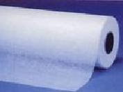
Glass Fiber Surfacing Tissue from Feicheng Lianyi Engineering Plastics Co Ltd

The Processing technology peculiar to the glass fiber surfacing tissue determines it possessing the characteristics of the leveled surface,the even fiber distribution,the soft feel,the good air permeability,and the quick speed of resin soaking.etc.The surfacing tissue is applied in the FRP,its good air permeability can make the resin to be permeated quickly,throughout eliminate the appearances of the bubbles and the white stains,its good die-fitting capabilty is suitable for the surfaces of any products with conplicated shapes,which can cover the cloth veins,increase the degree of finish and the anti-permeability of its surfaces,at the same time,strength the layer's shearing strength and the surface's tenacity,so that to cause the product's corrosion and temperature resistivities to be raised to some extent,it is really the necessaries in the manufacturing of the high quality FRP dies and its products.
Physical and Chemical Properties:
Items
Unit
Technical Specifications
30
40
50
60
Fiber Diameter
um
9-13
9-13
9-13
9-13
Weight
g/m2
30±3
40±4
50±5
60±6
Tensile Strength
N/50mm
≥16
≥20
≥25
≥32
Quantity of Organism
%
6-12
6-12
6-12Glass Fiber Surfacing Tissue
6-12
Water Rate
%
≤0.5
≤0.5
≤0.5
≤0.5
Soaking time (second Layer)
S
≤14
≤25
≤28
≤32


Paper pipe internal Diameter
mm
75
75
75
75

Hand Tools for Soil Boring

Exploratory holes into the soil may be made by hand tools, but more commonly truck- or trailer-mounted power tools are used. in this post hand tools are discussed. 


Hand Tools 


The earliest method of obtaining a test hole was to excavate a test pit using a pick and shovel. Because of economics, the current procedure is to use power excavation equipment such as a backhoe to excavate  

Undrained shear strength for anisotropic soils
Undrained shear strength for anisotropic soils.


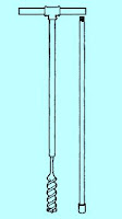
Helical hand auger tools for soil exploration


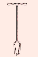
Posthole hand auger tools for soil exploration
*
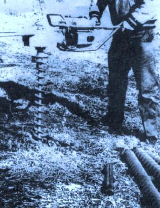
Gasoline-engine-powered hand auger withadditional auger flights in the foreground together with hand-driven sample tube

the pit and then to use hand tools to remove a block sample or shape the site for in situ testing. This is the best method at present for obtaining quality undisturbed samples or samples for testing at other than vertical orientation (Topmost Fig.). For small jobs, where the sample disturbance is not critical, hand or powered augers (See fig: Helical, Posthole and Gasoline-engine powered hand tools ) held by one or two persons can be used. Hand-augered holes can be drilled to depths of about 35 m, although depths greater than about 8 to 10 m are usually not practical. Commonly, depths are on the order of 2 to 5 m, as on roadways or airport runways, or investigations for small buildings.

Foundation Excavation Difficulties of World Trade Center's twin towers

The world's tallest buildings, the World Trade Center's twin towers, once stood on one of the biggest, had most complex foundations of that time. 

To install the foundations, a joint venture of five contractors working for the Port of New York Authority dug 70 ft into Manhattan's west shore to remove 1.2 million cu yd of rock and earth from a box-shaped excavation. The box was lined with 3,000 ft of cutoff wall that had a 64-ft head of water outside-and no internal bracing. 

All of the digging had to do over, under and around a pair of subway tunnels that carry nearly 600 commuter trains through the excavation daily. Without interruption of train traffic, the live and dead loads of about 1,000 ft of each tube must be had to transfer from the soil to a suspension system that held the tubes about 30 ft in the air for the next 2 years. 
Steel rises for north tower while south tower area is dug
The cutoff wall, which Icanda, Ltd., an affiliate of Icos of Milan, Italy, installed by the slurry methods, was roughly 3 ft thick and completely encircles a 1,000 x 500-ft area. Though its base was keyed about 3 ft into rock, the wall itself was not withstand the hydrostatic pressures from without. Therefore, the Port of New York Authority (PNYA) engineers designed a system of exterior anchors that will support the wall until the complex's heavily reinforced subfloors take over the job.
Because the cut-off walls are virtually impervious, the contractors' water problems were limited pretty much to handling the water trapped within them. Therefore, except in the areas of the subway tubes, where water elevation was extremely critical, the dewatering is routine. 

Initially the contractor installed four deepwell sumps 8 ft sq. The sumps did dewater adjacent areas, but no more, because of the impermeability of the ground. This was not serious, however, since 2-in, and 4-in, centrifugal pumps in local areas controlled the water. 

PNYA specifications called for lowering the water table outside the excavation to a depth of 5 to 10 ft. Rather than install well points all around the perimeter, the contractor had Icanda cast a 4-in, hole in each 22-ft wall section. With these open, the water from outside ran into the excavation, where the pumps sent it through a header system to the Hudson River nearby.

Precautions During Excavation of Foundation Work

Foundation transmits load of super structure to soil. Generally it is below the ground level. If some part of foundation is above ground level, it is also covered with earth filling. This portion of structure is not in contact of air, light etc, or to say that it is the hidden part of the structure.


The depth and width of foundation should be according to structural design.

-The depth of the foundation should not be less than 1 meter in case the design is not available.


-The length, width and depth of excavation should be checked with the help of center line and level marked on the burjis.


-The excavated material/ earth should be dumped at a distance of 1 meter from the edges. Work should be done on dry soil. 


-Arrangement of water pump should be made for pumping out rain water. 


-The bottom layer of the foundation should be compacted. 


-There should be no soft places in foundation due to roots etc. 


-Any soft/ defective spots should be dug out and be filled with concrete/ hard material

Factors Considered to Calculate Depth of Foundation

Foundation is the part of structure below plinth level up to the soil. It is in direct contact of soil and transmits load of super structure to soil. Generally it is below the ground level. If some part of foundation is above ground level, it is also covered with earth filling. This portion of structure is not in contact of air, light etc, or to say that it is the hidden part of the structure.

Depth of foundation depends on following factors:


1. Availability of adequate bearing capacity


2. Depth of shrinkage and swelling in case of clayey soils, due to seasonal changes which may cause appreciable movements.

Shore protection to provide safety against excavation cut of near by foundations of buiiding
3. Depth of frost penetration in case of fine sand and silt.


4. Possibility of excavation close by


5. Depth of ground water table


6. Practical minimum depth of foundation should not be less than 50 cm. to allow removal of top soil and variations in ground level.

7. Hence the best recommended depth of foundation is from 1.00 meter to 1.5 meter from original ground level.

Tectonics of Great Canadian earthquake (Magnitude 8.1) 1949 August 22

Local Date and Time: August 21, 1949 at 08:01:12 pm Pacific time

UT Date and Time: 1949-08-22 04:01:12 UT

Magnitude: Mw 8.1; Ms 8.1

Maximum Intensity: (Modified Mercalli) VII-VIII

Location: 53.62° N 133.27° W


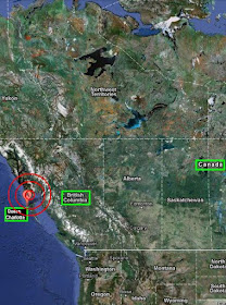
Canada's largest earthquake (magnitude 8.1) since 1700, occurred on August 22, 1949 off the coast of BC. It occurred on the Queen Charlotte Fault (Canada's equivalent of the San Andreas Fault) - the boundary between the Pacific and North American plates that runs underwater along the west coast of the Haida Gwaii (formerly Queen Charlotte Islands)
  off the west coast of British Columbia.
canada earthquake 1949 August 22
The shaking was so severe on the Haida Gwaii that cows were knocked off their feet, and a geologist with the Geological Survey of Canada working on the north end of Graham Island could not stand up. Chimneys toppled, and an oil tank at Cumshewa Inlet collapsed. In Terrace, on the adjacent mainland, cars were bounced around, and standing on the street was described as "like being on the heaving deck of a ship at sea". In Prince Rupert, windows were shattered and buildings swayed.

Dosages of Silica Fume in Concrete Industry

Silica fume acts as a filler and as a cementitious material in concrete. The small silica fume particles fill spaces between cement particles and between the cement paste matrix and aggregate particles. The silica fume also combines with calcium hydroxide to form additional calcium hydrate through the pozzolanic reaction. Both of these actions result in a denser, stronger and less permeable material.

Adding Silica Fume to concrete render more durability, improve resistance to corrosion and as discussed above reduce concrete permeability. In case of shotcrete application provide less rebound.

Dosages:
10% to 15%
High strength structural columns
10%
Flatwork
8% to 10%
High durability / Low permeability such as bridge decks or parking structures
8% to 15%
by weight of cement but as an addition not replacement
Microsilica concrete with steel fibre reinforcement
Silica Fume has been used as an addition to concrete up to 15 percent by weight of cement, although the normal proportion is 7 to 10 percent. With an addition of 15 percent, the potential exists for very strong, brittle concrete. It increases the water demand in a concrete mix; however, dosage rates of less than 5 percent will not typically require a water reducer. High replacement rates will require the use of a high range water reducer.

Microsilica Grade 97

Micro silica Grade97 is a dry powder powder. Micro silica Grade97 is a pozzolanic material that consists primarily of fine silicon dioxide particles in a non-crystalline form. Micro silica Grade 97 contains a minimum of 97% silicon dioxide (SiO2). 

Microsilica Packing: 500kg/jumbo bags or 20kg or 25kg small plastic woven bags.

Technical Data :
Analysis/Properties
Standard Value
SiO2(Silicon Dioxide)
Typical 97.24%
C(Carbon)
Max. 0.7%


Micro Silica Grade 97
Fe2O3 (Iron Oxide)
Typical 0.071%
Al2O3(Aluminium Oxide)
Typical 0.044%
CaO(Calcium Dioxide)
Typical 0.18%
MgO(Magnesium Dioxide)
Typical 0.18%
K2O(Potassium Dioxide)
Typical 0.38%
Na2O(Sodium Dioxide)
Typical 0.13%
Mn2O3(Mananese Oxide)
Typical 0.033%
P2O5(Phosphorus Pentoxide)
Max. 0.1%
SO3(Sulphur Trioxide)
Max. 0.2%
Cl (Chloride)
Typical 0.014%
Moisture Content(H2O )
Max. 0.5%
Loss on Ignition(L.O.I)
Typical 1.83%
pH Value
6-8
Percent Retained On 45μm (325 sieve)
Max. 0.5%
Bulk Density
200-350kg/m3