Effective Area of Groove Welds

Effective area of groove welds shall be considered as the effective length of the welds times the effective throat thickness. The requirements for groove welds are stated here following AWS : D 1.1 : Structural Welding Code-Steel.

The effective length of groove weld shall be the width of the part joined.

The effective throat thickness of a complete penetration groove weld shall be thickness of the thinner part joined.

The effective throat thickness of a partial-penetration groove weld shall be as shown in Table-1.

Table-1: Effective throat thickness of a partial-penetration groove welds.

Welding Process
Welding Position
Include Angle of Root of Groove
Effective throat Thickness
Shielded Metal Arc

Submerged Arc

Gas Metal Arc


Flux-Cored Arc


All
J or U Unit


Depth of Chamfer

Bevel or V
joint ≥600

 
Bevel or V
joint <600 ≥450
Depth of Chamfer minus 3 mm.
`
The effective throat thickness of a flare groove welds when flush to the surface of bar or 900 bend in a formed section shall be as shown in Table-2. Random sections of a production weld for each welding procedure, or such test sections as may be required by design documents, shall be used to verify that the effective throat is consistently obtained.

Table-2: Effective throat thickness of a Flare groove welds.
Type of Weld
Radius (R) of Bar or Bend
Effective throat Thickness
Flare Bevel Groove
All
5/16 R
Flare V- Groove
All
½ R*
Use 3/8 for Gas Metal Arc Welding (except short circuiting transfer process when R≥12mm.

Limitations
The minimum effective throat thickness of a partial penetration groove weld shall be as shown in Table-3. Minimum effective throat thickness is determined by the thicker of the two parts joined, except that the weld size need not exceed the thickness of the thinnest part joined though a large size is required by calculation. For this exception, particular care shall be taken to provide sufficient pre-heat foe soundness of the weld.

Table-3: Minimum effective throat thickness of a partial-penetration groove welds.
Material Thickness of Thicker part joined, mm
Minimum Effective Throat Thickness,mm
To 6 Inclusive
3
Over 6 to 12
5
Over 12 to 20
6
Over 20 to 40
8
Over 40 to 60
10
Over 60 to 150
12
Over 150
16

The Speed of Seismic Waves in Decreasing Sequence

Whenever the earth is suddenly struck or disturbed  due to earthquake vibration are produced. These vibrations are setup or start from a limited area and are propagated outward in all directions. Thus an earthquake may be defined as the passage of these vibrations in the earth.

when P-waves and S-waves reach the earth's surface, most of their energy is reflected back. Some of the energy is returned back to the surface by reflections at different layers of soil and rock. Shaking is more severe (about twice as much) at the earth's surface than at substantial depths. This is often the basis for designing structures buried underground for similar levels of acceleration than those above the ground.

Contact Pressure On Saturated Clay

The soil reaction beneath footing produce a upward pressure which is assumed uniform in deriving different relationship for soil-structure interaction problem. This pressure is called contact pressure. 


Flexible Footing

When a footing is flexible, it deforms into shape of bowel, with the maximum deflection at the center. The contact pressure distribution is uniform.


Rigid Footing

When a footing is rigid, the settlement is uniform. The contact pressure distribution is minimum at the center and the maximum at the edges. The stresses at the edges in real soils can not be infinite as theoretically determined for an elastic mass. In real soils, beyond a certain limiting value of stress, the plastic flow occurs and the pressure becomes finite.
Fig: Qualitative contact pressure distribution under flexible and rigid footing resting on saturated clay and subjected to a uniformly distributed load q.

Poly-Carboxylate Superplasticizer as Water Reducer for Concrete

Poly-carboxylate-based water reducer is a Light Yellow Powder having packaging details of 25kg/bag 1fcl=17mt. It is a kind of superplasticizer emerged in the early 80' s. It is mainly used in cement concrete. In chemistry, Poly-carboxylate-based is an organic and polymeric electrolyte. It belongs to a polymer surfactant. Therefore, it can also be applied in other paste materials such as gypsum products and ceramic products to reduce water content.
Poly-carboxylate is a weak electrolyte. It can only be fully dissolved in an alkaline solution .It can complex with cations in cement/water system to control the cement hydration process and thus to reduce the slump loss of the concrete. Poly-carboxylate achieves its water reducing effect through the yield of electrostatic repulsion and steric hindrance when it is absorbed to the cement particles. Hence, Poly-carboxylate is the most effective superplasticizer for cement concrete.
Poly-carboxylate is a raw material for superplasticizer. It is recommended that applicants should determine the Poly-carboxylate dosage in their own formulation according to their trial runs.

Limitation of Sand Drain Application

Following consideration is not included in design of sand drains:
1) 1) Secondary consolidation is not taken into account in the design of sand drains. In fact, the sand drains are ineffective in controlling the secondary consolidation for highly plastic and organic soils.
2) 2) In case of deriving equation for effectiveness of sand drains, it is not considered that the excess pore water pressure developed, actually in soil where sand drains are exist, is generally less than that of the case having no sand drains. Sand drains tend to act as weak piles and reduce the stresses in the clay.
3) The typical design parameter for sand drain may vary as below :
a) Spacing of sand drains, S = ( 2 ~ 5) m
b) Depth of sand drains, 2 H = (3 ~ 35) m 
c) Radius of sand drains well, rw = (0.2 ~ 0.3) m
d) Thickness of sand blanket = (0.6 ~ 1) m

Soil Classification Based on Composition

The earth is covered with different variety of soils. It is desirable to systemize or classify the soils into broad groups of similar behavior. it is more convenient to study the behavior of groups than that of individual one. Chemical constituents present in the soil are considered in the classification based on composition. It includes the following types:

a) Black soil

b) Lateritic soil

c) Pedzol

d) Peat soil

a) Black soil

The clayey soil having colored and formed from the basic igneous rock like. Basalts is a example of black soil. It mainly consists of iron, aluminum , magnesium, calcium oxides and also some organic matter. Its capacity to retain water is high. Also it swells considerably coming in contact with water. It is highly fertile and well known for growing cotton.


b) Lateritic Soil


It is brown colored soil derived from laterite and mainly consists of iron and aluminum hydroxide having a small percentage of manganese hydroxide, titanium oxide, silica, calcium, magnesium etc. it is not much suitable for agricultural works.


c) pedzol

it is a sandy soil of light grey color, with very small percentage of iron and organic content. Being deficient in nutritions components, this soil is not good for agricultural works.


d) Peat soil

This is a dark brownish colured soil formed by the decomposed vegetation matter. Thus, it is rich in organic content with very little sand and clay etc. it is highly porous with good water retaining capacity. For agricultural works it is not very fertile. Being soft and weak it readily subsides under loads.

Properties of Clay

The clay size (particles 0.002 mm and smaller) overlaps the silt sizes somewhat. The essential difference between the two, however, is that a clay mineral is not inert. It is a complex hydroaluminum silicate,

Al2O3 . nSiO2 . kH2O

where n and k are numerical values of attached molecules and vary for the same mass. The clay mineral has a high affinity for water, and individual particles may absorb 100+ times the particle volume. The presence or absence (during drying) of water can produce very large volume and strength changes. Clay particles also have very strong interparticle attractive forces, which account in part for the very high strength of a dry lump (or a clay brick). Water absorption and interparticle attraction collectively give the activity and cohesion to clay (and to soils containing clay minerals).

What is Seismic Secondary Waves( S-Waves)?

Whenever the earth is suddenly struck or disturbed  due to earthquake vibration are produced. These vibrations are setup or start from a limited area and are propagated outward in all directions. Thus an earthquake may be defined as the passage of these vibrations in the earth.


Details of Seismic Secondary Waves are:

1) Nature: These are transverse or distortional in nature. Therefore it is known as transverse waves, shear waves or shake waves.

2) Direction of Particle Vibration: The rock particles vibrate at right angles to the direction of propagation like light waves.

3) Speed: These travel slower than the P-waves and are second to be recorded.

4) Example: In granites, S-waves have speed of about 3 km/sec.

5) Penetration capacity: These can pass through solids but it is in capable of passing through liquids.

Underground and Overhead Telephone Cables

Unlike other services such as water, gas and electricity, telephones cannot be connected to a common mains supply. Each telephone requires a pair of wires connecting it to the telephone exchange. The external supply service and connection to the lead-in socket is carried out by telecommunication engineers. Internal extensions can be installed by the site electrician.

Typical Supply Arrangements:


Opening Effects of Slab on Its Strength

The effect of openings on the shear strength as well as flexure action (in case of large opening) of slab must be investigate carefully. The effect becomes severe when the openings are within the column strip areas of slabs or within middle strip areas when the opening are closer than 10 times the slab thickness(10h) from a column, measured radial.

To account for reduction of shear strength, it is considered that a portion of the critical section b0 is ineffective which is enclosed by straight lines projecting from the column centroid to the edges of the opening. If two much resisting perimeter is lost, the designer must be sure adequate tow-way bending is really present; otherwise the lower shear permitted in beams become the limiting values for the slab.

For slabs with shear reinforcement, the ineffective portion of the perimeter b0 is one-half of that without shear reinforcement. One-half factor is interpreted to apply equally to shearhead reinforcement and bar or wire  reinforcement.


Code Recommendation (ACI-318)


13.5.2.4 Where opening in slabs are located at a distance less than 10 times the slab thickness from a concentrated load or reaction area or when opening in slabs are located within column strip, the critical sections shall be modified as follows:

1) For slabs without shearhead, that part of the perimeter of the critical section that is enclosed by straight lines projecting from the centroid of the column, concentrated load or reaction area and tangent to the boundaries of the opening shall be considered ineffective.

2) for slabs with shearheads, the ineffective portion of the perimeter shall be one-half that defined in (1) above.

Geotechnical Properties of Black Cotton Soil

From Mineralogical analysis it is found that black cotton  soils consists of  kaolinite and montmorillonite. High percentage of montomonillonite renders high degree of expansiveness. These property results cracks in soil without any warning. These cracks may sometimes extent to severe limit like ½” wide and 12” deep. So building to be founded on this soil may suffer severe damage with the change of  atmospheric conditions.

SI No.
Description of properties
Value
1
Shear strength
Soaked CBR of only 1.5%,
2.
Residual strength parameter Φr
12°
3.
Permeability
10−10 cm/sec
4.
Liquid limit (Indian subcontinent)
40% ~ 100%.
5.
Free Swell index
Sometimes > 50%
An increase in lime content of 0 to 9% results in plasticity index to decreases from 47% to 5% and linear shrinkage to decreases from 11 to 3.6%  respectively.
As plasticity index and linear shrinkage decreased with the increase of lime content, a mixture of both lime and cement is necessary for adequate stabilization of road bases for heavy wheel loads on the black cotton soils. Previously derived results from African and Indian black cotton soils are also matched with these results.
black cotton soil

Structure:

we have already noticed that black cotton soils of different region show considerable variation of properties. So while explaining any property, we will try to mention region where the tests were conducted.

In Hyderabad, the formation of this soil is similar to lentil seed; their subsurface structure takes shape like double-convex lens.

What is Seismic Primary Waves( P-Waves)?

Whenever the earth is suddenly struck or disturbed  due to earthquake vibration are produced. These vibrations are setup or start from a limited area and are propagated outward in all directions. Thus an earthquake may be defined as the passage of these vibrations in the earth.


Details of Seismic Primary Waves are:

1) Nature : These are longitudinal or compressional in nature. Therefore it is known as longitudinal waves or compressional waves.

2) Direction of Particle Vibration
: The rock particles vibrates in the direction of propagation of the waves, with a push and pull effect.

3)
Speed
: It is the fastest waves and therefore first to be recorded at the recording station. It travels with about the same speed as sound through same rock.

4)
Example :
In granites, P -waves have speed of about 4.8 Km/Sec.

5)
Penetration Capacity
:
These waves are capable of passing through solids as well as liquides.

Construction Considerations for Adjacent Footing and Property Lines

An existing structure may be damaged during construction of new footing due to vibration, undermining or lowering of water table. The damage to the existing structure becomes greater with the increase in depth of new footing and with the decrease of distance of new footing to it. More severe condition arises when new footing is lower than existing footing.

The damage can be omitted by taking the precaution stated below:

a) The new footing if it is possible, should be placed at the same depth as the old ones and the sides of excavation adjacent to the existing structure should be suitably supported.


b) If the footings are placed at different levels, the slope of line joining the two footings should not be steeper than two horizontal to one vertical.

Specification of Poly-Carboxylate Superplasticizer for Cement Concrete.

Poly-carboxylate-based water reducer is a Light Yellow Powder having packaging details of 25kg/bag 1fcl=17mt. It is a kind of superplasticizer emerged in the early 80' s. It is mainly used in cement concrete. In chemistry, Poly-carboxylate-based is an organic and polymeric electrolyte. The specification of Poly-carboxylate is listed as follows.


Items
Specification
Visual Appearance Light Yellow Powder
Density 51 0 ± 10 /m 3
pH 9. 0 ± 0.5
Solid Content % 98. 0 ± 1.0
Cl - % 0.10
Na 2 SO 4 % 4.0
Na 2 O+0.658K 2 O % 5.0
Viscosity 11 ± 2
Stability Stable
Performance
Dosages for P.O 42.5 Standard Cement: (wt% of cement)
0.2 0 ± 0.02
Cement Paste Flow 240
Water Reducing Of Mortar 20

History of Dam Failure

The failure of the dam may be caused either due to bad workmanship or due to faulty design or due the occurrence of unanticipated floods. Luckily, these disasters have been comparatively rare in this century. Dams used to give away in olden times, but due to engineering advancement in modern times their failure has been considerably reduced taking care of design, keeping in view the various forces which are going to face, proper and rational design, good supervision and constant vigil and watch during maintenance periods ensures their safety. The Boulder Dam on Colorado River in U.S.A can not fail in one attempt, how furiously these river may try to move their foundations. But sometimes we have to pay for this confidence with tragedies.


Malpasset Dam

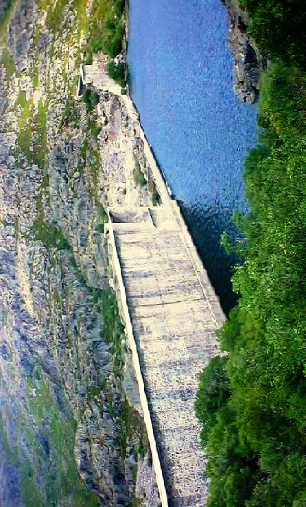
The "Reyran" river flowing well few hundred meters below the dam.


In 1954 the Malpasset Dam, a 200 feet high arch dam on the Reyran river, was completed. This dam failed in December 1956 causing 421 persons to die in floods. This was due to failure of foundation.


Vega de Tera Dam
A very confident dam called Vega de Tera Dam in Spain failed in January 1959. The town Rivaldelago was fattened. Telephone poles were snapped like matchsticks. With in moments, 123 villages were drowned. Several hundred luckier ones were saved, but were rendered homeless. This time this dam was not built strong enough to bear the full weight of its intended reservoir. Heavy rains wrecked it.

Vega de Tera Dam
Sometimes excessive and unanticipated earthquakes may result failure to a dam. In 1968 earthquake, the Koyna Dam in india was at the verge of failure. The engineers saved that dam by toiling hard day and neight.
Shakidor Dam Brust
The other failures are South Fork Dam due to spillway design error, Shakidor Dam due to extreme rainfall and Dale Dike reservoir, Taum Sauk pumped storage plant due to human, computer or design error.

Shadow Zone of Earthquake

In 1910 a seismic wave shadow zone was discovered while measuring how P and S waves travel through the earth and out the other side,. The shadow zone is the area of the earth from angular distances of 104 to 140 degrees from a given earthquake that does not receive any direct P waves. The shadow zone results from S waves being stopped entirely by the liquid core and P waves being bent (refracted) by the liquid core.


From the lack of S waves and a great slowing of the P wave velocity (by about 40%) it was deduced that the outer core is made of liquid. The shadow zone also defined the diameter of the core.

Sodium Naphthalene Formaldehyde Admixture for Concrete

SNF full name is Sodium Naphthalene Sulfonate formaldehyde condensate. Its high purity makes cement particles with high dispersancy, low foaming, high range water reducing and obvious strengthening so that we can get advantages of accelerating project mould turnover and construction speed, and also saving cement, improving cement mobility and workability. SNF is a high range concrete admixture of concrete cast-in-place, prefabricating, pump and curing.

Sodium Naphthalene Formaldehyde has two Specs as flws:

1)Sodium Sulphate 5%
2)Sodium Sulphate 18%

Item
Specification
Appearance yellow beige powder
Fluidness (mm) 240 min
Water exudation rate: 90%max
Gas content 3.0%max
Solid content 90%min
Sodium Sulphate 5%max / 18%max
Cl 1.0%max


Technical features & adaptability: 
1. Mixing amount: 0. 5-1. 0% of cementing materials, reducing rate: 20-30%
2. Keeping concrete strength intact & mixing this product, cement saving amount can reach 15-20%
3. Mixing this product 0. 7% (solid content) , slump constant increases above 10cm
4. Adapting to high strength, early strength, flowing, prefabricating & curing and prestressing force concretes etc.
Before using this product, please read precaution first.

Application:
SNF has a good adaptability to various cements and it is no erodent to reinforcing bar and nonpoisonous and pollution-free. SNF has been applied to the highway, bridge, tunnel, water conservancy hydroelectric project, port, quay, skyscraper, power engineering, industrial and civil building, prestressing force component and high range concrete etc.

Code’s Recommendation for Placement of Opening in Slab

As far as possible, opening in slabs should be located in zones where shear stresses are small and bending moment are below maximum. However, small opening for pipe sleeves etc. can be made anywhere in slab. In case of slabs supported directly by columns, from structural view point, they are best located well away from the columns, preferably in the area common to the slab middle strips. Opening of any size may be provided in slab systems if shown by analysis that the design strength is at least equal to the required strength and that specified limits on deflection meets. For strength the strip method is appropriate.

Code Requirements (ACI 318)
13.5.1 Opening of any size are permitted in slabs if analysis shows that both strength and deflection are acceptable.

13.5.2 In lieu of special analysis as required by 13.5.1 opening may be provided in slab systems without beams only in accordance with the following.


13.5.2.1 Opening of any size may be located in the area common to intersecting middle strips.

13.5.2.2 In area common to intersecting column strips, not more than 1/8 the width of column strip in either span shall be interrupted by openings.

13.5.2.3 In the area common to one column strip and one middle strip, opening size is limited to 1/4 the width of column strip in either span.

What is Slab?

Slabs are used to furnish a flat and useful surface in reinforced concrete construction. It is broad, flat plate, usually horizontal, with top and bottom surfaces parallel or nearly so. It may be supported by reinforced concrete beams, by masonry or reinforced concrete walls, by structural steel members, by directly by columns or continuously by the ground.

Slabs in which the deflected surface is predominantly cylindrical is called one-way slabs spanning in the direction of curvature. This condition arises when slabs are supported on two opposite sides, and those supported on all four sides with the longer span greater than twice the shorter span and also in cantilever slabs. In many cases, rectangular slabs are of such proportions and are supported in such a way that two-way action results. when loaded, such slabs bend into a dished surface i.e., an any point the slab is curved in both principal directions, and since bending moments are proportional to curvature, moments also in both directions.

Concrete slabs may in some cases be carried directly by columns, without the use of beams or girders. Such slabs are called flat plates. In some cases, to reduce the stresses due to shear and negative bending around columns, a thickened slab region in the vicinity of column and flared column tops are incorporated. Such construction is called flat- slab construction.

Modified Mercalli Seismic Intensity Scale

Intensities portray the effects of an earthquake in a particular location. These effects include potential damage, perception of shaking and permanent changes in topography. The most popular intensity scale used in the United States is the Modified Mercalli Scale (MMI) first developed in 1931.


MODIFIED MERCALLI INTENSITY SCALE 
MMI Value
Full Description
I
People do not feel any earth movement.
II
Felt by persons at rest, on upper floors of tall buildings 
III
Felt by people indoors.  Hanging objects swing back and   forth. 
Vibration from the earthquake may seem like the passing of light 
trucks. May not be recognized as an earthquake.
IV
Hanging objects swing.  Vibration may seem like   the   passing 
of heavy  trucks  or  a jolt, like  a  heavy  ball striking  the walls.   
Parked vehicles may  rock noticeably. Windows, dishes, doors 
may rattle and glasses clink.  In the upper range of IV, walls of 
wood frame buildings may creak.  
V
Almost everyone feels movement whether inside or outdoors. 
Sleeping  people  are  awakened.  Liquids  in  containers  are 
disturbed;    some  are  spilled.  Small   unstable  objects  are 
displaced   or   overturned. Doors   swing,   close,  or   open.   
Shutters, pictures on the wall move. 
VI
Almost everyone feels movement whether inside or outdoors. 
Sleeping   people  are  awakened.  Liquids  in containers are 
disturbed;   some are   spilled.  Small   unstable  objects  are 
displaced   or   overturned.  Doors  swing,  close,   or  open.   
Shutters, pictures on the wall move. 
VII
People  have  difficulty  standing. Drivers   on   the  road feel 
their cars shaking. Furniture  may  be  overturned and broken. 
Loose bricks fall from buildings and masonry walls and cracks 
in plaster   and  masonry  may  appear.  Weak chimneys may 
break at the roofline.  Damage  is  slight  to  moderate in well-
built structures; considerable in  poorly  constructed  buildings 
and facilities.
VIII
Drivers have trouble steering. Tall   structures such as towers, 
monuments  and  chimneys   may  twist and fall. Wood frame 
houses  that  are not bolted to their foundations may shift and 
sustain  serious  damage.  Damage   is   slight to  moderate in 
well-constructed buildings,considerable in poorly constructed 
buildings. Branches are broken  and  fall from trees. Changes 
occur in flow or  temperature  of   springs and  wells. Cracks 
appear in wet ground and on steep slopes. 
IX
Masonry  structures  and  poorly  constructed  buildings suffer
serious  damage  or  collapse.  Frame  structures, if not bolted, 
shift   off     foundations.     Serious   damage    to    reservoirs.   
Underground    pipes    broken.  Conspicuous  cracks  in   the   
ground. In  alluvial  areas, sand  and   mud  ejected  and  sand 
craters are formed.
X
Most masonry and frame   structures  destroyed   along   with 
their foundations.  Some   well-built  wooden   structures  and 
bridges are destroyed.    Serious  damage   to   dams,   dikes, 
and embankments. Large   landslides   occur.  Water  thrown 
on the banks of canals,  rivers   and  lakes.  Sand   and   mud 
shift horizontally on beaches and flat land.  Rails bent.