Mixing of Concrete

Purpose of Mixing:

The purpose of mixing is to coat the surface of all aggregate particles with cement paste and to blend all the materials of concrete into a uniform mass. In this process cement, water, fine and coarse aggregate and possible admixtures of uniform consistency are mixed intimately. Mixing can be continued for a considerable tune without adverse effect.

Concrete Mixer:
Several types of mixer is used in different construction purposes. Such as -
  • Tilting mixer
  • Non-tilting mixer
  • Pan type mixer
  • Continuous mixer
Nominal Size of Mixer:

This is described by the volume of concrete after compaction ( BS 1305 : 1974), which may be as low as one- half of the volume of the unmixed ingredients in a loose state. Mixer are made in a variety of sizes from 0.04 cum. If the quantity of mixed represents less than one-third of the nominal capacity of the mixer, the resulting mix may not be uniform, and the operation would, of course, be uneconomical. Overload not exceeding 10% is generally harmless.

Two-Stage Mixing:

The pre-mixing of cement and water allows better subsequent hydration and, when used for concrete, leads to a higher strength at a given water/cement ratio than conventional mixing. For instance, at w/c ratios of 0.45 to 0.5, a gain in strength of 10% has been observed. But, a large amount of heat is generated at very low w/c ratios. Moreover, two stage mixing undoubtedly represents a higher cost and is likely to be justifiable only in special cases.

Uniformity of Mixing:

Sufficient interchange of materials between different parts of the chamber is expected in any mixture to have a uniform concrete mix. The efficiency of mixer can be measured by the variability of the mix discharged into a number of receptacles without interrupting the flow of concrete.

Assessment of Performance of Mixers:

ASTM C 94-94

  • Samples of concrete should be taken from about 1/6 to 5/6 points of a batch
  • The difference in the properties of the two samples should be-
  1. Density of concrete ≤ 16 kg/
   2.Air content ≤ 1 percent

   3. slump ≤ 25 mm(l in)
when the average is under 100mm and 40 mm when the average is (100 ~ 150) mm
  • Percentage of aggregate retained on a 475 mm sieve ≤ 6 percent
  • Density of air-free mortar ≤ 1.6 percent
  • Compressive strength (average 7-day strength of three cylinders) ≤ 7.5 percent
BS 3963 : 1974(1980):

  • Water content as percentage of solids to 0.1 percent
  • Fine aggregate content as percent of total aggregate to 0.5 percent
  • Cement as percentage of total aggregate to 0.01 percent
  • Water/cement ratio to 0.01

Requirements for Shrinkage and Temperature Reinforcement for Concrete Member

Development of Shrinkage:

Hardening of concrete always associate with change in volume resulting shrinkage stresses. It is advisable to minimize such shrinkage by using concrete with the smallest possible amounts of water and cement compatible with other requirements, like strength and workability, and by thorough moist-curing of sufficient during. But a certain degree of shrinkage is usually unavoidable irrespective of what precaution are taken.

In case of slab having moderate dimensions freely rested on its supports can contract to compensate the shortening of its length produced by shrinkage. But in normal case, slabs and other members are joined rigidly to other parts of the structure and restricted to contract, producing shrinkage stress. In outdoor structures like bridges, a decrease in temperature relative to that at which the slab was poured subjected to similar effect of shrinkage.

Requirement of Reinforcement:


As concrete is weak in tension, the resulting stress of shrinkage produce cracks. Cracks of this nature are not detrimental provided their size is limited which is known as hairline cracks. The evenly distributed cracks are achieved by placing reinforcement in the slab to resist contraction.

Function of Steel as Shrinkage Reinforcement:


When the concrete tends to shrink, such reinforcement resists the contraction, subjecting to compression. The total shrinkage in a slab so reinforced is less than that in one without reinforcement.

However, if crack is produced, will be smaller width and more evenly distributed by virtue of the reinforcement.

Placement of Reinforcement:In slabs, provided with reinforcement provided for bending moments has the desirable effect of reducing shrinkage and distribution cracks. however, as contraction take place equally in all directions, it is necessary to provide special reinforcement for shrinkage and temperature contraction in the direction perpendicular to the main reinforcement. This added steel is known as temperature or shrinkage reinforcement.

CODE Requirements:Minimum Shrinkage and temperature reinforcement normal to primary flexural reinforcement is required for structural floor and roof slabs (not slabs on ground) where the flexural reinforcement extends in one direction only.

Acoustic Properties of Concrete

Acoustic properties have great importance in many building. This characteristics are mainly influenced by types of structure, construction details and properties of materials used in construction.

Acoustic Properties of a Building Materials
Generally, two properties are important in acoustic performance. These are-
  • Sound absorption
  • Sound transmission

Sound Absorption

energy created by sound waves is partly absorbed and partly reflected necessitating a sound absorption co-efficient, defining absorbed proportion of sound energy when hit a surface. Sometimes, a term "noise reduction coefficient" is used to define the average of sound absorption coefficients at 250, 500, 1000 and 2000 Hz is octave steps. This values are for
  • Normal wt. aggregate conc. having medium texture- 0.27
  • Expended shale aggregate - 0.45
When airflow is possible sound convert into hear by friction resulting large increase in sound absorption and this airflow depends on structure type, texure and porosity. Thus concrete made with porous light weight aggregate shows higher sound absorption than the cellular concrete contains discrete air bubbles.

Sound Transmission:It is measured in decibels(dB). the loss occur in sound transmission is a difference between the incident sound energy and the transmitted sound energy (which radiates into an adjoining room).

Rock’s Capacity to Retain and Yield Water

The properties of rocks which define water bearing capacity is porosity and permeability. To yield water easily a ground water bearing formation should not only hold water in sufficiently large quality, but also be capable to yield this water. Rocks have large variety of water bearing properties of different rocks are stated below:
1. Metamorphic Rocks:
Metamorphic rocks becomes good bearing formations when it is, to some external, weathered resulting considerable increment in their porosity and pore size. Gneiss and quartzite are very massive in nature and almost impervious. But presence of interconnected joints makes them previous and water retaining having a good yield.
Slates results good water bearing formations as they retain large amount of water along bedding planes and cleavage planes.
2. Sedimentary rocks:
The sedimentary rocks have the best water bearing formations as their porosity and permeability are yielding and retaining friendly.
The arrangement of sedimentary rocks in successive order of decreasing retaining and yielding capacity are as below:

The shales are porous but they are impervious in nature. The pore soak water by capillary action, but the pores are so minute that any yield is not possible.
3. Igneous Rocks:
Most of the igneous rocks have no pore resulting impermeability in nature. Only when interconnected joints and fissures present in such rocks circulation of water are generated providing a quick yield of water. Some times interconnected cavities may remain in some basalts and other volcanic rocks, which may retain large quantities of water.
Thus, in ground water exploration work, weathered metamorphic rocks are more promising than the fresh ones. In case of sedimentary rock loose and coarse formation are most promising ones. In massive igneous rock formations their joint patterns defines the accumulation and yielding of water.

Solution of Salt Water Intrusion in Ground Water in Coastal Areas

Salt Waters and Fresh Waters Relations in Coastal Area:Along coastal belt, a natural equilibrium between fresh and salt ground water is developed. The fresh water floats on the sea water as the specific gravity of sea water as the specific gravity of sea water is about 1.025. Hydrostatic equilibrium would require a fresh water column about 1.025 times as high as a salt water column, i.e. 1 ft of fresh water would exist above sea level for each 40 ft below sea level. Condition of hydrostatic equilibrium do not occur, however, because of hydraulic gradient imposed by the sloping water table. Magnification of the interfaces near sea level shows that fresh water is flowing out of the fresh water aquifer through a seepage face and across a portion of the ocean bottom into the ocean.

Thus the true shape of the interface is governed by hydrodynamic balance of the fresh and salt water. For most conditions, however, the 1/4o ratio rule may be applied without introducing serious error.

Problems Associated with Pumping:

Solution of Salt Water Intrusion in Ground Water in Coastal Areas
Equilibrium is disturbed, if the water table is lowered by pumping and an inverted core of salt water rises under the well. For equilibrium the salt water rises approximately 40 ft for each fact of drawdown in the fresh water. This severely limits the pumping rates of wells along coastlines.
Solution of Salt Water Intrusion in Ground Water in Coastal Areas
Solution :
Horizontal collectors or radial wells which operate with a small drawdown need not extend below sea level to avoid pumping salt water. This technique is widely used for the development of water supply on islands. Overdraft of the fresh ground-water may reduce the seaward gradient and permit the salt water to advance inland. Recharge wells along the coast have tried as a means of maintaining adequate fresh water to avoid saltwater intrusion. To prevent clogging from bacterial slimes and thus maintain satisfactory recharge, the water is chlorinated to about 6 mg/l . Some of the recharged water is wasted to the sea as part of the cost of salt water control. A similar problem is encountered in inland areas where salt water may remain in sedimentary rocks formed beneath the ocean or may have formed by solution of salts from surrounding rocks. Under these conditions pumping in adjacent freshwater aquifers must be limited to amounts which will not permit intrusion of the mineralized water.

Engineering Properties of Soil in Relation to Consistancy Limits

Definition of Consistency Limits:

The water content at which the soil changes from one state to other is known as consistency limits or Atterberg’s limits.

Atterbarg define these state as

  • liquid state
  • plastic state
  • Semi-solid state
  • Solid state

These limits are:

  • Liquid limit
  • Plastic limit
  • Shrinkage limit

Liquid limit:

The water content at which the soil damages from liquid to plastic state is known as liquid limit(LL). In this state, soil develop resistance to shear deformation.

Plastic limit:

The water content which brings soil from the plastic state to the semi-solid state is known as the plastic limit(PL). In this state, soil just fails to behave plastically.

Shrinkage limit:

The water content at which the soil changes from the semi-solid state to solid state is known as the shrinkage limit(SL).

Significance of Consistency Limits:

As the actual behavior of a soil depends upon its natural structure, the consistency limits do not give complete information about the in-situ soils. But these parameters are of great practical use as index properties of fine-grained soils. The index properties of such soils are related to the engineering properties as below:

1. Decrease in particle size increase liquid and plastic limits. But liquid limit increases at a greater rate resulting the rapid rate of increment in plasticity index.

2. Sandy soils, rather abruptly, changes from the liquid state to the semi- solid. These soil classified as non-plastic (NP).

Example: Soil having liquid limit less than 20% are generally sands

3. If organic matter is added, plastic limit of a soil increase, without any significant increase in liquid limit, i.e. soil with high organic content have low plasticity index

4. The compressibility of a soil is indicated by liquid limit, i.e. the compressibility of a soil generally increases with an increase in liquid limit.

5. The percentage of clay-size fraction present in the soil is directly proportional to shrinkage index. It defines the amount of clay.

6. Types and amount of clay in a soil is defined by liquid and plastic limit. But, plasticity index depends mainly on amount of clay, i.e. the plasticity index of a soil is a measure of the amount of clay in soil.

7. Liquid limit with plasticity index defines information about the types of clay. Classification of the grained soil can be obtain from plasticity chart.

8. When two soil have equal liquid limits, it observed that when plasticity index increase the dry strength and toughness increases, but the permeability remain almost the same.

9. If two soil of equal plasticity index is compared, it is noticed that as liquid limit increases, the dry streangth and toughness decrease, but compressibility and prmeability increase.

10. High percentage of colloidal clay containing mineral montmorillonite is defined by high toughness index.

Sub-surface Water

Definition:
Water in soil Mantle is called sub-surface water. About 30% of the world’s fresh water resources exist in the form of ground water. It gives important input for the substance of life and vegetation in barren zones. So, studies on various aspects of this sub-surface water is very important.


Forms of Subsurface water:


Sub-surface water is considered in two zones.


1) Saturated zone.


2) Aeration zone.


1. Saturated zone:


In this zone all the interstices of soil are filled with water. Here, the water table forms its upper limit and marks a free surface, i.e. a surface having atmospheric pressure.


2. Zone of aeration:


Interstices in soil only partially saturated with water, in this zone which extends between the land surface and the water table. The thickness of zone of aeration depend upon the soil texture and moisture content and may very from region to region. Again, the zone of aeration has three sub zones:


a) Soil water zone

b) Capillary fringe


c) Intermediate zone

Welding

Definition:

The method welding joints metals by fusion. The metals at the joint is melted and fues with additional metal from a welding rod using heat from either an electric arc or an oxyacetylene torch. The weld material and the base metal form a continuous and almost homogeneous joint after after cooling.

Shielded Arc Process:

A heavy coated welding rod is used that releases an inert gas which envelopes the arc stream to protect the weld from excessive oxidation. This techniques is called the shielded arc process.


1) Butt welds

The strength of a butt weld is equal to the allowable stress multiplied by the product of the length of the weld time the thickness of the thinner plate of the joint. The allowable stress is taken to be the same as that of the base metal.

2) Fillet welds

Normally side and transverse fillet welds are used in practical cases. The strength of side or transverse fillet welds is assumed to be determined by the shearing resistance of the throat of the weld regardless of the direction of the applied load. In the 450 fillet weld, with the leg equal to t, the shearing area through the throat depth
i.e. A = L( t sin 450)
= 0.707 L t.

Allowable stress for fillet welds
The allowable stresses for fillet welds specified by the AISC (based on recommendation of the American Welding Society) depending on the electrode used in the welding process and on the grade of steel being welded. For example, if E-70 electrode are used to weld A 36 steel ( one of the more grades of structural steel used today), the allowable shearing is 21 Ksi (145 Mpa). For this case, the strength and allowable force per unit length for the 450 fillet weld are as follows:

AISC specification for maximum size of fillet weld:


It is required to adopt special precautions to ensure that length of the leg of a fillet weld along an edge is actually equal to the thickness of the edge. This is because

1) The edge of rolled shapes is rounded and the length of the leg would be less than the nominal thickness of the shape.
2) During welding, the corner of the edge may melt into the weld; which would reduce the length of the leg. 

AISC specification

For material thickness  ≥  ¼ in.

The maximum size of a fillet weld should be 1/16 in. (2 mm) less than the material thickness along edges of ¼ in.( 6 mm) or more thick.

For material thickness  <  ¼ in.

For edges less than ¼ in. thickness, the maximum size of the weld may equal to the egge thickness.

However, weld size may exceed these specifications if the designer stipulates that the weld is to be built out to obtain full throat thickness .

Advantages of Welded Connection:

Welded connections are used extensively to supplement or replace riveted or bolted connections in structural and machine design. It is more economical to fabricate a member by welding simple component parts together than to use a completed casting and the dependance on welded connections is increased.

Behavior of Short Column During Earthquake

Short Column Effect:
The short column is stiffer as compared to the tall column, and it attracts larger earthquake force. Stiffness of a column means resistance to deformation. The larger the stiffness, larger is the force required to deform it. If a short column is not adequately designed for such a large force, it can suffer significant damage during an earthquake. This behavior is called short column effect. The damage in these short columns is often in the form of X-shaped cracking. This type of damage of columns is due to shear failure.
Result of Short Column Effect:
More damage are suffered in shorter columns compared to taller column in the same storey, is observed in previous earthquake. This situation occur when a building is rested on sloping ground. During earthquake shaking all columns along more horizontally by same amount along with floor slab at a particular level. But, if reinforced concrete frame buildings have column of different heights within one storey, the short columns attract several times larger earthquake force and suffer more damages as compared to taller ones. The short column effects also occurs in columns that supports mezzanine floors or soft slabs that are added in between two regular floors.
The Solution:
During architectural design stage the short column effect can be avoided in new structures. But when it is not possible this effect should be considered in structural design. The ACI code for ductile detailing of RC structures requires special confining reinforcement to be provided over the full height of column that are likely to sustain short column effect. The special confining reinforcement(i.e., closely spaced closed ties) must extend beyond the short column into the columns vertically above and below by a certain distance for details of special confinement reinforcement.

BIOGAS RECOVERY

In industrialized as well as developing countries the possibility of regaining energy, has prompted an interest in applying biogasification to waste treatment, in the form of the combustible gas methane. It serves a two fold function –
a) waste treatment
b) energy production
which have drawn attraction of this concept.
Process of Biogas Generation:
It is decomposition of organic matter of biological origin under anaerobic conditions with an accompanying production primarily of methane (CH4) and secondarily other gases, most of which is carbon dioxide (CO2).
In the anaerobic digestion, wastes are decomposed without oxygen at relatively high moisture contents ( 90 ~ 99.5 %). The wastes undergo decomposition and produce
- firstly organic acids
- then biogas from organic acids
The process also involves the breakdown of proteinaceous materials into amines and such fertilizers as nitrites and ammonia. These products are more easily available as nutrients for plants, than are the complex proteins in the original waste.
Stages in Conversion of Organic Substances:
In the conversion of organic substances into methane by biogas microbes, some stages are considered. These are –
a) fermentive bacteria
b) hydrogen-producing acetogenic bacteria
c) methane-producing bacteria
The stages are described below with related reactions:
a) Fermentive bacteria
In first stage of the biogas formation process a mixed group of bacteria involved which hydrolyze various complex organic substances and then ferment them to yield various volatile acids, hydrogen and carbon dioxide according to fallowing typical reactions:
C6H12O6+H2O ---» 2CH3COOH (acetic acid) + 2CO2 +4H2
C6H12O6 ---» CH3CH2CH2COOH (butyric acid) + 2CO2 +2 H2O
b) Hydrogen producing Acetogenic Bacteria
The substances produced in the first stage(such as propionic acid, aromatic acid, alcohol etc. which methane producing bacteria can not use) into acetic acid, hydrogen, carbon dioxide is decomposed by these bacteria. The reactions involved are:
CH3CH2COOH + 2H2O ---» CH3COOH + CO2 + 3H2
CH3CH2CH2COOH + 2H2O ---» 2CH3COOH + 2H2
c) Methane-producing bacteria:
Conversion of the substances produced in the First and Second stages (acetic acid, hydrogen, carbon dioxide, formic acid etc.) into methane and carbon dioxide is done these bacteria.
The bacterias are namely acetoclastic methane bacteria (acetophilic) and hydrogen-utilizing methane bacteria. The reaction involved are:

Fracture Toughness

Definition:

Fracture toughness is one of the most important properties of any materials for virtually all design applications which describes the ability of material containing a crack to resist fracture. It is a quantitative way of expressing a material’s resistance to brittle fracture when crack is present. If a material has large value of fracture toughness it will probably undergo ductile fracture.
Reason of Concrete Surfaces Cracking:

Improper design and construction practices cause majority of concrete cracks; such as :
1. Improper sub grade preparation.
2. The use of high slump concrete or addition of water on the job.
3. Improper finishing.
4. Inadequate or no curing.
5. Omission of isolation and control joints and improper jointing practices.
Material Susceptible to Low Fracture Toughness:

The high strength materials have low crack resistance (Fracture Toughness). i.e the residual strength under the presence of cracks is low. When only small cracks exists, structures designed in high strength materials may fail at stresses below the highest service stress, they were designed for. The structure is made fail safe by selecting materials with low growth rate and high residual strength and by adopting a design with inherent crack stopping capabilities.
Failure Mechanism:

Pre-existing crack will grow with time due to the application of repeated load or due to a combination of loads and environmental attack. The longer the crack, the higher the stress concentration induced by it. This implies that the rate of crack propagation will increase with time. The presence of crack reduces the strength of the structure. After a certain time the residual strength has become so low that the structure can not withstand accidental high loads that may occur in service.If such accidental high loads do not occur, the crack will continue to grow until the residual strength has become so low that fracture occurs under normal service loading.
Significance of Fracture Toughness:

Structural design must incorporate considerations of both the strength and durability of a component that contains cracks. The residual strength of a part in the presence of defects is a function of the material fracture toughness. So, to ensure the safety of a structure, the designer must estimate the load carrying capacity of a structure after the propagation of cracks.

The concrete industry and inspection agencies are much more familiar with traditional cylinder compression tests for control and acceptance of concrete.

Fracture toughness can be used for design purpose, but corresponding compressive strength must be considered. Anytime trial batches are made both fracture toughness and compressive tests should be made, so that a correlation can be developed for field control.

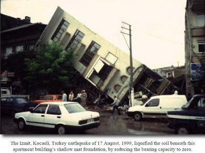
LIQUEFACTION

Definition
The condition, in which the soil has little or no shearing strength and will flow as a liquid is known as liquefaction.
Mechanism of liquefaction
strength of saturated cohesionless soils depends upon the effective stress acting between particles. When external forces cause the pore volume of a cohesionless soil to reduce the amount V, pore water pressures are increased during the time required to drain a volume V of water from the soil element. 
Consequently, pore pressure increases depend upon the time rate of change in pore volume and the drainage conditions (permeability and available drainage paths). When conditions permit the pore pressure, u, to build up to a value equal to the total stress, sn, on the failure plane, the shear strength is reduced to near zero and the mixture of soil grains and water behaves as a liquid.
Earthquakes in Kentucky
Consequence of liquefaction
Liquefaction or flow failure of sands involves a substantial loss of shearing strength for a sufficient length of time that large deformations of soil masses occur by flow as a heavy liquid. Stucture sink into soil or suffer excessive settlement, resting on such soil without considering liquefaction.

Liquefaction due to seismic activity
Soil deposits that have a history of serious liquefaction problems during earthquakes include alluvial sand, aeolian sands and silts, beach sands, reclaimed land, and hydraulic fills. During initial field investigations, observations that suggest possible liquefaction problems in seismic areas include low penetration resistance; artesian heads or excess pore pressures; persistent inability to retain granular soils in sampling tubes; and any clean, fine, uniform sand below the groundwater table. The liquefaction potential of such soils for structures in seismic areas should be addressed unless they meet one of the criteria in Table below . In the event that none of the criteria is met and a more favorable site cannot be located, the material in question should be removed, remedial treatment applied , or a detailed study and analysis should be conducted to determine if liquefaction will occur.

LIQUEFACTION

Table - Criteria for Excluding Need for Detailed Liquefaction Analyses
1. CL, CH, SC, or GC soils.
2. GW or GP soils or materials consisting of cobbles, boulders, uniform rock fill, which have free-draining boundaries that are large enough to preclude the development of excess pore pressures.
3. SP, SW, or SM soils which have average relative density equal to or greater than 85 percent, provided that the minimum relative density is not less than 80 percent.
4. ML or SM soils in which the dry density is equal to or greater than 95 percent of the modified Proctor (CE 55) density.
5. Soils of pre-Holocene age, with natural overconsolidation ratio equal to or greater than 16 and with relative density greater than 70 percent.
6. Soils located above the highest potential groundwater table.
7. Sands in which the "N" value is greater than three times the depth in feet, or greater than 75; provided that 75
percent of the values meet this criterion, that the minimum "N" value is not less than one times the depth in feet, that there are no consistent patterns of low values in definable zones or layers, and that the maximum particle size is not greater than 1 in. Large gravel particles may affect "N" values so that the results of the SPT are not reliable.
8. Soils in which the shear wave velocity is equal to or greater than 2000 fps. Geophysical survey data and site geology should be reviewed in detail to verify that the possibility of included zones of low velocity is precluded.
9. Soils that, in undrained cyclic triaxial tests, under isotropically consolidated, stress-controlled conditions, and with cyclic stress ratios equal to or greater than 0.45, reach 50 cycles or more with peak-to-peak cyclic strains not greater than 5 percent; provided that methods of specimen preparation and testing conform to specified guidelines.

EFFECT OF SEISMIC DEFORMATIONS IN STUCTURES

Earthquake causes shaking of the ground. So a building resting on it will experience motion at its base. From Newton’s First Law of Motion, even though the base of building moves with the ground, the roof has a tendency to stay in its original position. But since the column are connected to it, they drag the roof along with them. This tendency to continue to remain in the previous position is known as Inertia. In the building, since the walls or columns are flexible, the motion of the roof is different from that of the ground.

The inertia force experienced by the roof is transferred to the ground via the columns, causing forces in columns. These forces generated in the columns can also be understood in another way. During earthquake shaking, the columns undergo relative movement between their ends. This movement is shown as quantity u between the roof and the ground . But, given a free option, column would like to come back to the straight vertical position, i.e., columns resist deformations. In the straight vertical position, the columns carry no horizontal earthquake force through them. But, when forced to bend, they develop internal forces. The larger is the relative horizontal displacement u between the top and bottom of the column, the larger this internal force in columns. Also, the stiffer the columns are ( i.e.,bigger is the column size), larger is this force. For this reason, these internal forces in the columns are called stiffness forces. In fact, the stiffness forces in a column is the column stiffness times the relative displacement between its ends.

LIMITATION ON MATERIALS TO WITHSTAND EARTHQUAKE

A minimum specified concrete strength f΄c of 3000 psi and a maximum specified reinforcement yield strength fy of 60,000 psi are mandated. These limits are imposed as reasonable bounds on the variation of material properties, particularly with respect to their unfavorable effects on the sectional ductilities of members in which they are used. A decrease in the concrete strength and an increase in the yield strength of the tensile reinforcement tend to decrease the ultimate curvature and hence the sectional ductility of a member subjected to flexure. Also, an increase in yield strength of reinforcement is generally accompanied by a decrease in the ductility – as measured by the maximum deformation –of the material itself.


There is evidence suggesting that lightweight concrete ranging in strength up to 12,500 psi can attain adequate ultimate strain capacities. Testing to examine the behavior of high strength, lightweight concrete under high intensity,cyclic shear loads, including a critical study of bond characteristics,has not been extensive in the past. However, there are test data showing that properly designed lightweight concrete columns, with concrete strength ranging up to 6200 psi, maintained ductility and strength when subjected to large inelastic deformations from load reversals. It was felt by committee 318 that a limit of 4000psi on the strength of lightweight concrete was advisable, pending further testing of high strength lightweight concrete members under reversed cyclic loading. Note that lightweight concrete with a higher design compressive strength is allowed if it can be demonstrated by experimental evidence that structural members made with that lightweight concrete posses strength and toughness equal to or exceeding those of comparable members made with normal weight concrete of the same strength.

However, ASTM A 615 billet steel bars of Grade 40 or 60 may be used in these members if the following two conditions are satisfied :

Actual fy ≤ specified fy +18,000 psi
(actual ultimate tensile stress)/( actual fy) ≥12.5.
The first requirement helps to limit the magnitude of the actual shears that can develop in a flexural member above that computed on the basis of the specified yield value when plastic hinges from at the ends of a beam. The second requirement is intended to ensure steel with a sufficient long yield plateau.